API Fire Test Specification for Valves: API 607 VS API 6FA

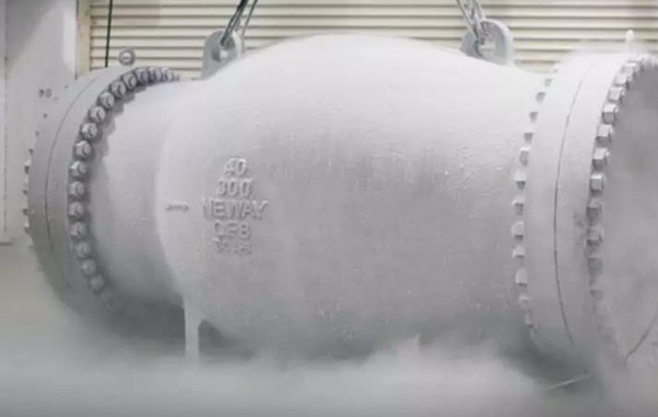
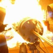
Valves used in some industries, such as the petrochemical industry, have the potential danger of fire, should be specially designed to make them still have certain sealing performance and operating performance under high-temperature fire. A fire safe test is an important method to measure the fire resistance of the valve. At present, there are There are several organizations who provides procedures
relevant to the testing of petrochemical equipment for its functionality when exposed to fire like API, ISO, EN, BS ect, of which they differ slightly in test methods and specifications. Today here we learn the requirements for API fire resistance test, including API 607, API 6FA, API 6FD. They are fire safe tests for valve 6D and 6A.

API 607-2010 Fire Test for Quarter-Turn Valves and Valves Equipped with Nonmetallic seats such as ball valve, butterfly valve, plug valve. Fire test requirements for actuators (e. g., electric, pneumatic, hydraulic) other than manual actuators or other similar mechanisms (when they are part of the normal valve assembly) are not covered by this standard. API 6FA applies to quarter-turn soft seated valves as covered in API 6D and API 6A, pipeline valves include ball and plug valves, for example, ball valves, gate valves, plug valves but check valves are not included and the fire test for check valves is specified in API 6FD. API 6A is the standard for wellhead and tree equipment safety valves, corresponding to ISO 10423 and API 6D is the standard for line ball valves, corresponding to ISO 14316.


Comparation of  API 607 and API 6FA

Specification API 607, 4ed API 6FA
Scope


DN for All

PN≤ANSI CL2500

DN for All
Sealing Soft sealed Not specified
End connection ANSI ANSI
Body material Not specified Not specified
Test liquid Water Water
Position of ball Closed Closed
Position of stem Horizontal Horizontal
Temperature 760-980℃ of flame

≥650℃ of body

760-980℃ of flame

≥650℃ of body

Burn period 30 minutes 30 minutes
Pressure during burn period Acc. to pressure rating

e.g ANSI 600=74.7bar

Acc. to pressure rating

e.g ANSI 600=74.7bar

Leakage test during burn period, internal Do not include company standards such as EXXON, SNEA  etc. Max 400ml*inch/min
Leakage test during burn period, external Max 100ml*inch/min Max 100ml*inch/min


For more information about the fire-resistant valve , feel free to contact us at [email protected] or visit our website: www.perfect-valve.com.

What’s steam trap?

Steam traps are a type of valve that automatically discharges condensate, air, and carbon dioxide gas from heating equipment or steam lines while minimizing steam leakage. Traps allow uniform heating of equipment or piping to prevent water hammer effect in steam pipelines. According to its mechanisms or operation principles, steam traps can be divided into floating ball steam traps, thermostatic steam traps, thermodynamic steam traps and so on. Different types of traps can be used to discharge the same amount of condensate under a certain pressure difference, each trap has its own advantages and the most suitable operating usage range depends on its temperature, specific gravities, and pressure.

Factors when choosing a steam trap

  • Drain water

The trap displacements are the steam consumption per hour multiplied by the maximum condensing water (2 to 3 times the selected multiplier). When the steam heating equipment starts conveying steam, the steam trap is required to quickly discharge air and low temperature condensed water to make the equipment gradually normal working. Air, low-temperature condensate and lower inlet pressure make trap overload operation when the boiler started, the requirements of the trap than the normal operation of the displacement of large, so generally choose the drain water in accordance with the 2-3 times of the steam trap. This ensures that the trap timely discharge of condensed water and improve thermal efficiency.

  • Operating pressure differential

Steam trap nominal pressure and working pressure differ variously because the nominal pressure refers to the pressure level of the steam trap body, so the engineer can not choose the steam trap based on the nominal pressure, but the working pressure differential. Working pressure difference equals working pressure in front of trap minus backpressure of trap outlet. The outlet back pressure is zero when condensate is discharged into the atmosphere behind the trap. If the condensate discharged by the trap is collected at this time, the outlet back pressure of the trap is equal to the resistance of the return pipe + the lifting height of the return pipe + the pressure in the second evaporator (return tank).

  • Working temperature

The engineer should select the steam trap that meets the requirements according to the maximum steam temperature. The maximum steam temperature exceeding the saturated steam temperature corresponding to the nominal pressure is called superheated steam. At this point, the special bimetal steam trap for high temperature and pressure superheated steam may be a better choice.

The superheater trap offers two obvious advantages: one is it can be used as a superheater header trap; the other is protecting the superheater tube to prevent overheat burning when starting and stopping of the furnace. Once started or stopped, the main valve is in a state of closure. If there is no steam flow cooling in the superheater tube, the tube wall temperature will increase, which may cause the superheater tube to burn out in serious cases. At this time, open the flow valve to discharge steam to protect the superheater.

  • Connections

The connection diameter of the trap is equivalent to the size of the drain water. The steam trap capacity with the same diameter may vary greatly. Therefore, the size of the maximum displacement and the condensate pipe diameter cannot be used to select the trap valve.


How does steam pressure reducing valve work?

Steam reducing pressure valves are valves that precise control the downstream pressure of steam and automatically adjust the amount of valve opening to allow the pressure to remain unchanged even when the flow rate fluctuates by pistons, springs or diaphragms. The pressure reducing valve adopts the opening and closing parts in the valve body to adjust the flow of the medium, reduce the medium pressure and adjust the opening degree of the opening and closing parts with the help of the pressure behind the valve, so that the pressure behind the valve remains in a certain range, in the case of constant changes in the inlet pressure to keep the outlet pressure in the set range. It is important to choose the right type of steam relief valve. Do you know why steam needs pressure-reducing?

Steam sometimes causes condensation, and condensed water loses less energy at low pressure. The steam after decompression reduces the pressure of condensate and avoids the flash steam when it is discharged. The temperature of saturated steam is related to pressure. In the sterilization process and surface temperature control of paper dryer, pressure relief valves are needed to control the pressure and further control the temperature. Some systems are with high-pressure condensate water to produce low-pressure flash steam to achieve the purpose of energy-saving when the flash steam is insufficient or steam pressure exceeds the set value where needs a pressure reducing valve.
Steam has a higher enthalpy at low pressure. The enthalpy value at 2.5mpa is 1839kJ/kg, and that at 1.0mpa is 2014kJ/kg when the low-pressure steam valve is needed to reduce the steam load of the boiler. High-pressure steam can be transported by pipes of the same caliber, which are denser than low-pressure steam. For the same pipe diameter with different steam pressures, the steam flow is allowed to be different, for example, the steam flow in DN50 pipe at 0.5mpa is 709kg/h, while that in 0.6mpa is 815kg/h. In addition, it can reduce the occurrence of wet steam and improve the dryness of steam. High-pressure steam transportation will reduce the size of the pipeline and save costs, suitable for long-distance transport.

The types of steam pressure reducing valve

There are many types of steam pressure reducing valve, they can be divided into direct-acting pressure reducing valve, piston pressure reducing valve, pilot-operated pressure reducing valve and bellows pressure reducing valve according to their structure.
Direct-acting pressure reducing valve has a flat diaphragm or bellow and does not need to install external sensing lines downstream because it is independent. It is one of the smallest and most economical pressure reducing valves, designed for the medium with low flow and stable load. The accuracy of direct-acting relief valves is usually +/-10% of the downstream set point.

When the reducing valve size or output pressure is larger, with the pressure regulating spring directly adjust the pressure will inevitably increase the spring stiffness, flow changes when the output pressure fluctuation and valve size will increase. These disadvantages can be overcome by the use of pilot-operated pressure reducing valves, which are suitable for sizes of 20mm or more, for long distances (within 30m), dangerous places, high places or where pressure adjustment is difficult.
The use of piston as the main valve operating parts to ensure fluid pressure stability, piston pressure relief valve is suitable for frequent use of the piping system. From the above function and applications, the purpose of pressure reducing valves can be summarized as “pressure stabilization, dehumidification, cooling” in the steam system. Steam pressure reducing valve for decompression treatment, basically is determined by the characteristics of the steam itself, also by the medium needs.

The sealing analysis of LNG cryogenic valve

Cryogenic valves are mainly concentrated in liquefied parts and LNG storage parts for natural gas liquefaction plants. Form a rough statistic, there are about 2,000 cryogenic valves available in LNG receiving stations (large stations with a receiving capacity of more than 2 million tons/year), accounting for more than 90% of all the valves. Among them, there are about 700 small-size valves, while the rest are high-pressure and large-diameter valves.

LNG has a small molecular weight, low viscosity, strong permeability, easy to leak, inflammable and explosive which requires high sealing of the valve, as well as static electricity, fire prevention and explosion protection. The seals play a central role in keeping valves up and running, today we analyze the sealing requirements of cryogenic valves in LNG system.


Stem Seal

The stem seal for cryogenic valves is usually packing. Common fillers are PTFE, impregnated PTFE asbestos rope and flexible graphite. To ensure its cryogenic seal performance, a combination of soft seal and hard seal double packing is often used, a double packing with intermediate isolation ring (low temperature and high-temperature resistant mixture) and the additional elastic load device. Elastic load device such as disc spring gasket, so that the packing in the low-temperature pre-tightening force can be continuously compensated, to ensure the packing sealing performance for a long time.

Valve leakage is divided into internal leakage and external leakage. The external leakage is more dangerous due to the flammable and explosive nature of LNG. Stem seal leakage is a major potential source of external leakage. Cryogenic valve stem seal can be metal bellows seal structure, that can work at high temperatures and low-temperature conditions. Compared with mechanical seals, bellows seal has the advantages of zero leakage, no contact, no friction, no wear and so on, which can effectively reduce the medium leakage at the valve stem and improve the reliability and safety of cryogenic valves.


Flange Seal

The ideal cryogenic seal gasket material is soft at room temperature, resilient at low temperature, with small linear expansion coefficient and certain mechanical strength. The middle flange gasket of the cryogenic valve is made of stainless steel ring and flexible graphite. At low temperatures, the gasket seal is smaller than the reduction which may cause the leakage of the medium.


Fasteners

Austenitic stainless steel fasteners should be selected to ensure the low-temperature impact toughness under LNG working conditions. It is necessary to go through strain hardening and molybdenum disulfide to the part of the thread because of the low yield strength of austenitic stainless steel.

Fully threaded studs are often used for valve fasteners. In order to improve the mechanical properties, raw material solution heat treatment (Class1), final solution heat treatment annealing (Class1A), final solution heat treatment annealing and tensile hardening (Class2) can be carried out for austenitic stainless-steel fasteners. Austenitic stainless steel fasteners of 304, 321, 347 and 316 below 1/2in (12.5mm) shall be used at temperatures above -200℃. If solution heat treatment or strain hardening has been done, the low-temperature impact test is not required, otherwise it should be conducted.

Fasteners are prone to fatigue failure under alternating load. Torque wrenches should be used in actual operation to ensure uniform force on each bolt and avoid leakage caused by excessive force on a single bolt.

What’s nitrogen blanketing valve?

Nitrogen blanketing valve also referred to as a nitrogen padding valve or “make-up” valve, is the valve which filling the empty space of a liquid storage tank with nitrogen gas. The nitrogen seal device is mainly mounted on the top of the storage tank to control the micro-positive pressure of the storage tank, isolate the medium from the outside, reduce the volatilization of the medium, and protect the storage tank. Nitrogen blanketing valve uses the energy of the medium itself as the power source without additional energy. The control accuracy of the valve is about twice higher than that of the general pressure control valve, with a large pressure difference ratio (such as 0.8Mpa in front of the valve and 0.001Mpa behind the valve). That is convenient, fast, especially suitable for micro pressure gas control, which can be set continuously in the running state. Automatically controlled nitrogen tank blanketing valve has been widely used in the continuous supply of natural gas, city gas and metallurgy, petroleum, chemical industry and other industries.

How does the nitrogen blanketing valve work?

(1)Nitrogen blanketing valve closing piston sealing in the valve room, when the tank pressure is greater than or equal to the setpoint, membrane jacking up, make the gas pilot valve sealing ring moving up tightly by the spring pressed on the seat and closed to control the nitrogen imports. At the same time, special valve core chamber pressure increases and close to the nitrogen gas manifold pressure, the pressure through the internal channels from the special valve core chamber to the main valve core chamber. Main valve spool gas pressure balance, tightly closed under the double action of gravity and spring.

(2)Nitrogen blanketing valve in the open state, when the tank pressure is slightly lower than the set pressure, be because of induction pressure drop and move down the driving guide valve is opened, the nitrogen export through the orifice plate and guide valve in to the tank to tank pressure increases, and gas chamber pressure drop, pilot valve core nitrogen through the internal channels from the special valve core into the main valve core chamber. Since the piston area of the main valve core is greater than the seat hole area of the main valve, and because of the spring and the weight of the main valve, the pressure in the special spool chamber and the main valve spool chamber decreases very little when the tank pressure is slightly below the set point, the main valve remains closed and nitrogen enters the tank from the air valve.

The tank blanketing valve is the main component of gas tank blanketing device. Nitrogen blanketing device is composed of a control valve, actuator, pressure spring, conductor, pulse tube and other components, mainly used to keep the nitrogen constant pressure at the top of the container, especially suitable for all kinds of large storage tank gas blanketing protection system. The nitrogen supply device introduces the medium at the pressure measuring point on the top of the tank through the pressure tube into the detection mechanism to balance with the spring and the preload. When the pressure in the tank is reduced to below the pressure set point of the nitrogen supply device, the balance is broken, the valve conductor is opened, so that the gas in front of the valve passes through the pressure relief valve, the throttle valve, into the upper and lower membrane chamber of the main valve actuator, the main valve spool is opened, and nitrogen is injected into the tank; When the pressure in the tank rises to the pressure set point of the nitrogen supply device, close the valve core of the conductor due to the preset spring force, and close the main valve and stop the nitrogen supply due to the spring action in the actuator of the main valve.


More information, contact PERFECT-VALVE 


What is bellow sealed valves?

The bellows valve’s stem is double sealed by the bellows and the packing, often used where it needs the strict sealing performance of valve stem. Metal bellows can produce the corresponding displacement under the action of pressure, transverse force or bending moment, and has the advantages of pressure resistance, corrosion resistance, temperature stability and long service life. Bellows can improve the sealing performance of the valve stem and protect it from the corrosion of medium, suitable for heat transfer media of polyester industry, ultra-vacuum and nuclear industry.

Toxic, volatile, radioactive media or expensive liquids that do not permit external leakage by reciprocating stem are often bellows sealed bonnet. This special bonnet design protects the stem and packing from contact with fluid while fitting the bellows seal element with a standard or environmentally-friendly packing box design to avoid the catastrophic consequences of bellows rupture failure. Therefore, engineers should pay attention to the stem packing leakage in order to prevent bellows failure. For wet chlorine gas and other occasions requirements are not particularly high, “rotary valve + multistage packing” can be used. Such as multistage flexible graphite packing of the full – function ultra-light control valve.

There are usually two structure types for bellows, welded and machined. The overall height bellows with welded stem is relatively low and it also has a limited service life due to its manufacturing method and internal structural defects; The bellows machined has a higher height, reliability and longer life. The pressure rating for bellows seals decreases with increasing temperature. It includes bellows seal single seat valve and bellows seal double seat valve.

When the bellow sealed valve manufacturing is completed, it must pass 100% pressure test and the test pressure is 1.5 times the design pressure; when it is used for steam, the 100% sealing test is essential and the sealing level must be higher than the level 4.

Bellows valve inspection

  • Parts inspection

The inspection and test of bellows and bellows assembly shall be divided into delivery inspection and type inspection. Unless otherwise specified, the inspection conditions shall be conducted under the conditions of the ambient temperature of 5 ~ 40 ℃, the humidity of 20 % ~ 80 % and an atmospheric pressure of 86 ~ 106 kPa. Type test takes three for cycle test and then takes the minimum value to calculate the minimum cycle life. If all three test pieces are qualified, the type test of the product of this specification is qualified. One of the three items is not up to standard. If two of the three tests are unqualified, the type test is judged to be unqualified. No leakage of inspection results is considered as qualified.

  • Sealing test

The bellows assembly and the valve stem were combined by welding by argon arc welding methods. The gas leakage test was conducted at 0.16mpa under standard atmospheric pressure and the ambient temperature of 20 ℃ for 3min. The test was conducted in the water tank, and the result was qualified for invisible leakage.

  • The whole machine test

Before assembly, the burr should be removed and all parts and body cavities should be cleaned. After assembly, the whole valve should be inspected and tested. The test result is qualified as the whole valve, surface polishing, cleaning, polishing, painting and packaging are allowed.