The lining material for the lined valve

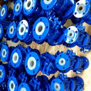
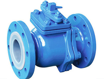
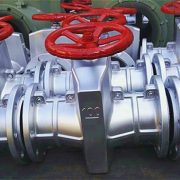
Lined valve, is a type of fluorine plastic lined corrosion-resistant valve, which lined fluorine resin (or by special processing) in steel or iron valve pressure bearing inner wall or the surface of inner parts bt the molding or injection process for strong corrosion medium. Simply put, the lining material needs to be filled in the valve body where the medium can reach. Fluorine lined valves can be used in all concentrations of sulfuric acid, hydrochloric acid, hydrofluoric acid, aqua regia and various organic acids, strong acids, strong oxidants, and other solid media, but is limited to temperature (for medium-range form -50℃to150℃). The valves that can be manufactured with lined plastic include lined butterfly valves, lined ball valves, lined globe valves, lined plug valves, lined gate valves, lined cock valves, etc. There are many fluorinated materials that can be used for lining valves. The most commonly used materials are FEP (F46) and PCTFE (F3). Today, we will introduce the characteristics and applications of these materials for you, if interested in, please read on!


Materials Working temperature Working conditions Features
PTFE(F4) -180~200℃ Strong acid, base,  oxidant, etc Excellent chemical stability and corrosion resistance, good electrical insulation, heat resistance, self-lubricity;

Corroded by molten alkali metal, low friction coefficient, but poor fluidity, large thermal expansion, need sintering molding instead injection molding.

PVC 0~55℃ Resistant to water, alkali, non – oxidizing acid, chain hydrocarbon, oil and ozone High mechanical strength, excellent chemical stability and electrical conductivity, good aging resistance, easy fusion and bonding, low price.
FEP(F46) -85~150℃ Any organic solvents or reagents, dilute or concentrated inorganic acids, bases, ketones, aromatics, chlorinated hydrocarbons, etc.; The mechanical and electrical properties and chemical stability are basically similar to F4, but with high dynamic strike toughness and excellent weather resistance and radiation.
PCTEF(F3) -195~120℃ Various organic solvents, inorganic corrosion fluids (oxidizing acids) The heat resistance, electrical property and chemical stability are next to F4, and the mechanical strength, creep property and hardness are better than F4.
PVDF(F2) -70~100℃ Most chemicals and solvents Good toughness, easy to form. Tensile strength and compression strength are better than F4 and can withstand bending, radiation, light and aging, etc
RPP -14~80℃ An aqueous solution of inorganic salts, dilute or a concentrated solution of an inorganic acid/base; One of the lightest plastics. Its yield, tensile and compressive strength and hardness are better than those of low-pressure polyethylene.

Good heat resistance, easy to form, cheap price. It’s dynamic impact, fluidity and bending elastic modulus are improved after modification, .

PO -58~80℃ Various concentrations of acid, alkali salts and some organic solvents; The most ideal anticorrosive material has been widely used in rotary forming large equipment and pipelining.


More about the lined valve or want a quick inquiry, contact us now!

What’s the Eccentric semi-ball valve used for?

The eccentric semi-ball valve is consist of the valve body, eccentric shaft, valve cover, semi-ball, bushings, valve seat, and other parts, it rotates the eccentric shaft by 90 °to open/close the valve to cut off the medium, suitable for sewage disposal, petroleum, chemical, electricity and paper industries processing of slurry, slurry ash, paper pulp, alumina and other sealing tightness occasions, especially in two-phase flow medium. According to its installation structure, the eccentric semi-ball valve can be divided into a top entry eccentric semi-ball valve and side entry eccentric semi-ball valve.

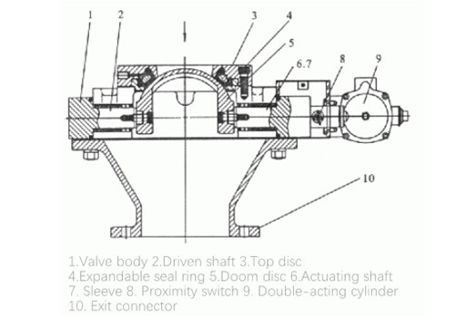
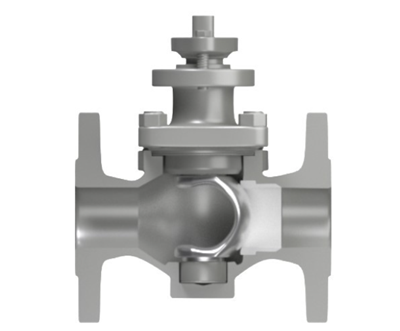
The design of the eccentric ensures no friction between the valve seat and semi-ball during opening or closing, extending the valve serving life. There is a certain eccentricity between the rotation of the eccentric axis and the center of the valve body, that is, the half-ball changes the axial displacement with the change of angular displacement when it is opened and closed so that they are in a linear proportional relationship, and its motion path is a semi-parabolic trajectory. The trajectory of the hemispheric body from the lowest point to the highest point automatically wedges the seat, and the seat also automatically generates a preload depending on the elastic modulus of the material to close tightly.

Eccentric semi ball valve provides many advantages like, simple structure, lightweight, small resistance and torque, tight sealing, easy online maintenance, just open the valve cover and take out the eccentric shaft. The semicircular port has good flow performance and linear regulation performance, and impurities will not be deposited in the valve body cavity. In addition, she has the function of cutting, that is, in the closing of the media can be cut off debris, to ensure the normal opening and closing of the valve. The semi-ball and seat of the valve can be surfacing with different alloys to meet the needs of different occasions.


Design and manufacture: MSS SP-108

Size: DN2″-40″

PN: CLASS150-CLASS900


Materials

Part Material
Valve body WCB、A105
Shaft 420、410
Disc Nitriding steel, wear-resistant steel
Seat Nitriding steel, wear-resistant steel
Bearing Aluminum – bronze
Packing PTFE、Flexible graphite


Specifications

PN(Mpa) 0.6 1.0 1.6 2.5 4.0
DN(mm) 40-600 40-600 40-600 40-600 40-600
Sealing test pressure(Mpa) 0.66 1.1 1.76 2.75 4.4
Body test pressure(Mpa) 0.9 1.5 2.4 3.75 6.0
Working temperature(℃) -29~300、-29~425、-29~540
Medium Liquids like seawater, sewage, acid and alkali or slurry, steam, gas, oil, mud, ash etc.
Operation Handwheel, electric, pneumatic
Connection Flanged, wafer
Installation Vertical and horizontal


Size

PN(MPa) DN(mm) Size (mm)
d1 L D D1 D2 D6 f f2 b Z-φd H1 H2
1.6 25 25 150 115 85 65 2 14 44 75
32 32 165 135 100 78 2 16 48 105
40 40 180 145 110 85 3 16 48 95
50 50 200 160 125 100 3 16 48 107
65 65 220 180 145 120 3 18 48 142
80 80 250 195 160 135 3 20 88 152
100 100 280 215 180 155 3 20 88 178
125 125 320 245 210 185 3 22 88 252
150 150 360 280 240 210 3 24 8-23 272
200 200 400 335 295 265 3 26 12-23 342
2.5 25 25 150 115 85 65 2 16 44 75
32 32 165 135 100 78 2 18 48 85
40 40 180 145 110 85 3 18 48 95
50 50 200 160 125 100 3 20 48 107
65 65 220 180 145 120 3 22 88 142
80 80 250 195 160 135 3 24 88 152
100 100 280 230 190 160 3 28 8-23 178
125 125 320 270 220 188 3 30 8-25 252
150 150 360 300 250 218 3 34 8-25 272
200 200 400 360 310 278 3 34 12-25 342
4.0 25 25 150 115 85 65 58 2 4 16 44 75
32 32 180 135 100 78 66 2 4 18 48 107
40 40 200 145 110 85 76 3 4 18 48 95
50 50 220 160 125 100 88 3 4 20 48 107
65 65 250 180 145 120 110 3 4 22 88 142
80 80 280 195 160 135 121 3 4 22 88 152
100 100 320 230 190 160 150 3 4.5 24 8-23 178
125 125 400 270 220 188 176 3 4.5 28 8-25 252
150 150 400 300 250 218 204 3 4.5 30 8-25 272
200 200 502 375 320 282 260 3 4.5 38 12-30 342


What’s dome valve?

In the field of power, metallurgy, chemical, food, pharmaceutical and other industries, there are often need to transfer high-temperature particles or powder raw materials to the specified container, where a quick cut-off valve, dome valve is needed can be used here to cut off the medium and obtained sealing.

It can cut off the flowing material into the pressure tank or close to achieve sealing so as to ensure the filling rate of the pressure tank is 100% without a material level gauge, safe and reliable. The inflatable pressure sealing ring embedded in the dome seat ensures the working pressure difference between upstream and downstream of the valve and avoids the abrasion of the sealing ring. The dome valve is mainly operated by pneumatic actuators, the linear cylinder or sector cylinder is fully closed driven, which offers a large output torque. When the valve is opened and closed, there is no contact between the valve core and the inflatable rubber sealing ring, reliable sealing performance and can work under severe working conditions.

Working principle:

The ball valve is opened/closed with a gap of about 2mm between the spool and the rubber seal ring, allowing them to move in a contactless manner without causing or reducing wear. Fully sealed straight or sector cylinder drives the dome valve to rotate, effectively preventing dust caused by wear, leakage, etc. When the dome valve is closed, the rubber seal ring inflates, expands, and presses tightly against the spherical dome spool, forming a reliable seal ring band that prevents material flow.

Features of the dome valve:

1. Lightweight, fast action, switch only 5~8 seconds, valve drive pneumatic, is the ideal part in the pipeline automation system;

2. The ball has no friction with the sealing ring in the whole process of opening and closing, which improves the service life of the valve to a limited extent;

3. Upper and lower stem bushings are self-lubricating, with small friction coefficient, flexible opening and closing, and reliable sealing performance;

4. The valve switch signal device can realize remote automatic control. Integrated and quick connector for easy operation.


Specifications:

DN, mm 50 80 100 150 200 250 300
Working pressure, MPa ≤1.0
Working temperature ℃ ≤200
Air source Pressure, MPa 0.4~0.6
Gas consumption, L/time 1~3
Medium Granule, dry ash, dry powder materials, etc
Material Valve body: WCB;

Doom: WCB+Chromeplate/Ni60

Seat: Butyl rubber/Viton

Stem/bonnet/York: A105

Cylinder: Aluminum alloy

Notes: The filling pressure of the rubber sealing ring should be 0.30 ~ 0.60MPa and higher than the conveying pressure 0.15MPa, the working pressure of the cylinder should be 0.45 ~ 0.65MPa, and the compressed air should be clean, dry and oil-free.


What’s pinch valve?

Pinch valve, also known as hose valve, is a unique structure of the valve that consists of aluminum alloy/cast steel body, rubber sleeve, valve stem gate, guide pillar and other parts. With the features of convenient opening, good sealing performance and cost-saving, the pinch valve is an economical alternative to a gate valve, globe valve and regulating valve, which can extend the5-10 times of service life than that of conventional valves, suitable for conveying system of granular slurry or chemical medium in low-pressure pipeline.

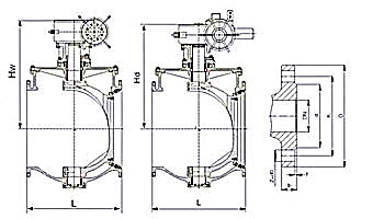
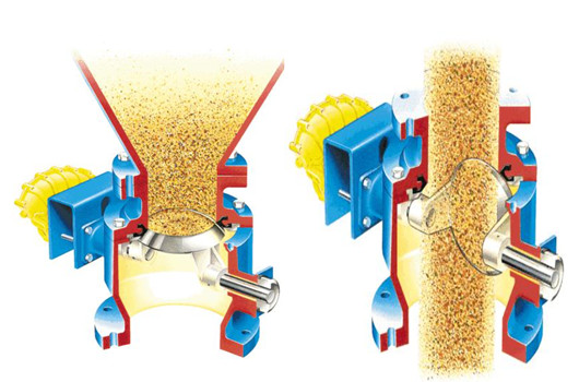
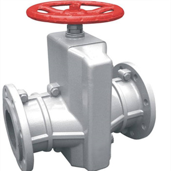
The rubber sleeve is the core part of the pinch valve, which can be replaced regularly, saving cost, with excellent corrosion resistance, wear resistance and good bearing pressure. There are several sleeve materials can be selected according to the corrosiveness and abrasiveness of the flow media, and the operating temperature. The EPDM rubber pinch valve is designed for the higher temperature environment, which needs to be within the limit of the polymer. In addition, electric, pneumatic, manual or hydraulic actuator drives the sleeve to achieve opening, close and adjusting action.


The principle of pinch valve

For a manual pinch valve, when the handwheel turns, the stem forces the internals to force the rubber sleeve and the gate to reciprocate between the guide pillars to close the valve. Similar principle for the pinch valve with actuator, the force pushing down onto the rubber sleeve which fully collapses and closes tightly.


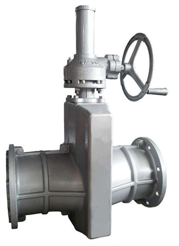
The features of pinch valve

  • Full port or bore, no obstruction
  • Low flow resistance, sleeve self-cleaning
  • Zero leakage can be closed when there are residual particles;
  • No clogging or dead spots to prevent valve operation
  • Simple design, not affected by the external environment.
  • Replaceable elastomer sleeve, low and easy maintenance cost.


The applications of pinch valve

Pinch valves are commonly used in the pipeline transportation of some corrosive chemical media, or abrasive solid or liquid products such as particles, fibers, powders and mortar. It can also be used in sewage processing such as sludge treatment, gravel cleaning, raw sewage, lime, charcoal. The typical application including:

Power plant: FDG system, ash removal system, coal transport;

Mining: Tailings filling, flotation control, mud line, or other slurries;

In addition, it is also widely used in cement, glass, paper manufacturing, electronics industry, food industry, and industrial sewage and other fields.


The extraction check valve for high pressure turbine

In the last article, we introduced the ventilator valve, blowdown valve and reverse flow valve for turbine system, here today we will continue talking about the extraction check valve for high-pressure turbine When the valve opens, the cylinder takes steam, the flowing medium pushes the valve plate to open the valve, the greater the medium flow, the greater the spool opening; When the valve is closed, the solenoid valve quickly loses power and expunges the air in the cylinder. In addition to the dead weight of the valve plate and the auxiliary closing force of the cylinder, the valve is quickly closed.

The high-pressure turbine steam-exhaust check valve is installed in the horizontal pipeline of the steam turbine reheating and cooling section to prevent water and steam from pouring back into the high-pressure cylinder and affecting the safety of the steam turbine. Specially designed for steam turbine exhaust protection, their fast and tight closure ensures that water or steam can be quickly isolated from the steam turbine while the generator is tripped or the main steam valve is closed. The valve will close automatically when the high water level of heating equipment in the turbine tripping or all levels of extraction steam pipelines. As a protective device, the extraction check valve must be reliable.


High-pressure cylinder exhaust steam pressure: Reheater inlet pressure

High-pressure cylinder exhaust temperature: ≤420℃

Extraction pressure of each section: vacuum ~10MPa

Extraction temperature of each section: 200~510 ℃

Valve pressure range:

ASME B16.34 1996 –150 Class

ASME B16.34 1996 – 300 Class

ASME B16.34 1996 –400 Class

ASME B16.34 1996 –600 Class

Valve body: Cast steel

ASTM A216-WCB

ASTM A217-WC6/WC9(1# /3#extraction)

Actuator:

For large units, the steam extraction reverse check valve is mainly driven by pneumatic, while it is hydraulic for small and medium-sized units.


The type of extraction check valve 

According to the opening /closure parts:

  1. Self-weight closing. Self-weight close (close): Check valve closed by the self-weight or counterweight of the trim or depending pressure of medium and counterweight of trim to keep it in the open position of the valve.
  2. Power-assisted closing. The actuator provides a pulse point action to make the spool overcome the initial inertia caused by being in the closed position for a long time or external causes and complete the rest travel by itself to close the valve.
  3. Power closing. During the closing process, the actuator always provides power to complete all the travel of the spool and close the valve.

According to its structure:

  • Steam extraction reverse check valve without a hammer

IBS internal balancing shaft steam extraction reverse check valve without a hammer. Internal balance refers to the internal balance of the dead weight of the spool. The spool is supported by the shaft and rotates freely around the shaft. They are not connected directly but are connected with the piston of the side working cylinder. The actual opening inside the valve cannot be confirmed.

  • Steam extraction check valve with a heavy hammer

A large diameter valve offers heavy trim, then a heavy hammer can be used in the extraction steam check valve, hammer can offset part of the trim weight (about half of the spool). The valve trim is directly connected to the shaft, and the actual opening inside can be seen from the angle changes of the exterior tumbler. If the inside is not fully open, it can be observed from the outside. The valve is a free swing, gravity closed check valve, when the inlet pressure is higher than the outlet valve trim open, while the valve closed on the contrary.

The pressure reducing valve VS overflow valve

Both the pressure reducing valve and overflow valve can be used to regulate the pressure and maintain the safety of the pipeline. The pressure reducing valve is a pressure regulating valve that makes the valve outlet pressure lower than the inlet pressure, mainly used to reduce the pressure of a branch oil line in the hydraulic system to make the branch pressure is lower than the main pressure and stable. The disc of pressure reducing valve in the valve body reduce the medium pressure and adjust the opening degree under the downstream pressure, so that the downstream pressure remains in a certain range, to keep the outlet pressure in the set range in the case of constant changes in the inlet pressure.

The overflow valve, also known as the relief valve, an automatic pressure relief device driven by the static pressure in front of the valve. It opens proportionally as the pressure exceeds the opening force, mainly used for fluid applications. It is mainly used for constant pressure,overflow and safety protection in the hydraulic system.

Quantitative pumps provide constant flow in the throttling control system. When the system pressure increases, the flow decreases. At this point, the overflow valve is opened to make the excess flow overflow back to the tank, ensuring that the inlet pressure of the overflow valve constant, that is, the pump outlet pressure. When it is used to limit the pressure, it can be used as a safety valve. When the system is working normally, the overflow valve is in the state of closure and started when the system pressure is greater than its set pressure, which offers overload protection for the system. The differences are:

  1. Different working purposes. The overflow valve is usually connected in parallel with the branch of the system to prevent system overload and ensure safety. Pressure-reducing valves are generally connected in series on a certain road to reduce pressure under the premise that the system cannot be loaded. It can be said that the former is passive work, and the latter is active work.
  1. The pressure reducing valve maintains the pressure at the outlet unchanged, while the overflow valve maintains the pressure at the inlet unchanged;
  2. The pressure reducing valve is normally operated, reducing pressure through the narrow channel. The overflow valve is normally closed and only acts when the system is overpressurized.