What’s orifice valves and what’s used for?

Orifice valve is a type of flow metering throttling device which can measure all single-phase fluid including water, air, steam, oil, etc., has been widely used in power plants, chemical plants, oil fields and natural gas pipelines. Its working principle is that when the fluid with certain pressure flows through the orifice part in the pipeline, the locally contracts flow rate increases and the pressure decreases, resulting in the differential pressure. The greater the fluid flow velocity, the greater the differential pressure. There is a definite functional relationship between them and the fluid flow can be obtained by measuring the differential pressure.

Orifice flow system consists of an orifice throttling device, transmitter and flows computer. The flowrate measurement range of orifice flowmeter can be extended or transferred by adjusting the orifice opening diameter or the range of the transmitter within a certain range that can reach 100:1. It is widely used in situations with a large range of flow variations and can also calculate the bidirectional measurement of fluid.


Advantages and disadvantages of orifice valves

Advantages:

  • The throttling parts need not be calibrated, accurate measurement and the calibration measurement accuracy can be 0.5;
  • Simple and compact structure, small size and lightweight;
  • Wide application, including all single-phase fluid (liquid, gas, steam) and partial multi-phase flow;
  • The orifice plate with different apertures can be changed continuously with the change of flow rate and can be checked and replaced online.

Disadvantages:

  • There are requirements for the length of the straight pipe section, generally more than 10D;
  • Non-recoverable pressure drop and high energy consumption;
  • Flange connection is prone to leakage, which increases maintenance cost;
  • The orifice plate is sensitive to corrosion, wear and dirt, and may fail in the short term to heating water and gas (deviation with actual value)


More information, contact PERFECT-VALVE 

Ventilator valve, blow down valve and reverse flow valve for turbine system

As a prime mover for large, high-speed operations, the steam turbine is one of the main devices in today’s coal-fired power plants, used to drag generators to convert mechanical energy into electrical energy. The steam turbine is characterized by a large volume and fast rotation. When it is transferred from the static state of normal temperature and pressure to high temperature and high-pressure high-speed operation, the regulating valve of the steam turbine plays a key role in stabilizing the speed and controlling the load. Only the stable and accurate operation of the valve can make the steam turbine work safely and efficiently. Today here we will introduce the three main valves like ventilator valve, blowdown valve and reverse flow valve for you, if interested, please read on.


Ventilator valve(VV)

When the middle-pressure cylinder of the unit starts to operate under low load, the high-pressure cylinder has no steam or less steam intake, and the vent valve is closed. This will cause the blade of the high-pressure stage to overheat due to friction blast. At this time, install a ventilation valve in the exhaust pipe of the high-pressure cylinder to keep the vacuum, similar to a blower, so that there is a little steam or air as possible in the high-pressure cylinder to reduce the blast. It connects the high-pressure cylinder with the condenser vacuum to prevent friction or excessive blast exhaust temperature when the load is low.

In addition, after the steam turbine trip, the ventilation valve automatically opens and the high-pressure cylinder steam quickly flow into the condenser, the turbine high-speed low-steam flow will have a blast of friction high tail blades to prevent because of the high-pressure steam pressure cylinder shaft seal leakage through high school into the intermediate pressure cylinder (the middle-pressure cylinder for vacuum) caused by rotor speed. It can also be used to prevent speeding.

In addition, after the steam turbine tripping, the ventilation valve automatically opens and the steam in the high-pressure cylinder is quickly discharged into the condenser. At the time of high-speed and low-steam, the air blast friction heat generated at the tail end of the high-pressure blade is reduced to prevent the steam from leaking into the middle-pressure cylinder (vacuum state) through the high-pressure cylinder shaft seal, resulting in the rotor Overspeed. It can also be used to prevent speeding.

High-pressure discharge ventilation valve is generally used in the unit in the middle-pressure cylinder or high-pressure cylinder combined with the beginning of the open to prevent air friction metal overheating (especially at the end of the high-pressure cylinder blade) caused by damage due to too little steam. In order to prevent over speed after slugging, some units can also open the ventilation valve to quickly drain the high exhaust steam. Some units also need a ventilation valve to take the heat away from the cylinder after the quick cooling after the shutdown, which is then discharged into the expanding container and finally into the condenser.


Blow down valve(BDV)

For high and middle-pressure cylinder units, in order to prevent the high-pressure cylinder and steam pipe tube of a small amount of steam channeling to the middle-pressure cylinder, the low-pressure cylinder, or the steam seal gap is large and the unit overspeed due to the steam seal tooth wear. Where a blow down valve(BDV) is installed. When the unit trips, the BDV valve opens quickly to direct the remaining steam from the high/medium pressure steam seal to the condenser to prevent the unit from overspeed. The opening and closure of blow down valve are controlled by the stroke of medium pressure regulating valve oil motor:

When the stroke of the oil motor of the middle pressure regulating valve is ≥30mm, the BDV valve is closed;

When the stroke of the middle pressure regulating valve oil motor is <30mm, the BDV valve opens.

The solenoid control valve provides a working magnetic field when compressed air enters the upper piston of the valve. When the electromagnetic control valve loses its magnetism, the upper part of the piston of the BDV valve is communicated with the exhaust and the air pressure is released. The piston moves up to open the valve under the action of the spring force.


Reverse flow valve (RFV)

There are no bearings between the high and medium pressure cylinders, which are communicated through the steam components of the rotor shaft seal. When the steam turbine is tripping under high load, the high and medium pressure regulating valve quickly closes and cuts off the steam turbine to prevent overspeed. However, at this time, the medium pressure cylinder is a vacuum, which causes the high-temperature/high-pressure steam of the high-pressure cylinder to return and leak from the shaft seal and continue to expand, thus causing overspeed. To prevent this from happening, a pneumatic BDV can be installed in operation when the pressure regulator valve closed, most of the leakage of steam directly to the exhaust device. When starting in a cold state, the auxiliary stream is led to the high-pressure discharge reverse valve through the RFV valve and discharged through the high-pressure inner cylinder steam trap and the high-pressure steam guide pipe steam trap.


More information, contact us now!

What’s explosion-proof valve?

Explosion-proof valves are used in underground coal mines or other inflammable and explosive occasions such as dust removal systems containing combustible media and can be used as pressure relief devices for explosive pipelines or equipment. General explosion-proof valves generally include two kinds of valves, one is in the possibility of explosion when the valve automatically operate to eliminate the source of the explosion, such as the safety valve installed in the boiler or dust collector in front of the flue, of which automatic release pressure, when reached a specified value to prevent the pressure, is too high or cause an explosion.


The explosion-proof valve is used in the dust removal system for containing combustible gas or combustible material and can be used as a pressure relief device for explosive pipelines or equipment. The diaphragm of the explosion-proof valve is usually calculated according to the operating pressure of the dust removal system and the content of combustible substances, generally can be divided into the installation structure can be divided into the horizontal explosion-proof valve and vertical explosion-proof valve, they are composed of steel welded barrel and explosion-proof valve, electromagnetic valve. As the name implies, the vertical explosion-proof valve is installed on the barrel vertically, while the horizontal explosion-proof valve is installed on the top of the pipeline. This explosion-proof valve is mainly used in the hydraulic system of equipment without a mechanical locking system, such as a large mechanical stage, lifting machine, elevator, automobile inspection and maintenance girder, etc.

The other type of explosion-proof valve is that will not produce high heat or electric sparks when working or the valve of which actuator can meet explosion-proof standards. There are typical explosion-proof ball valves, explosion-proof gate valve, or explosion-proof butterfly valves that fitted with electric or pneumatic actuators to prevent or delay an explosion. Among them, the most commonly used electric explosion-proof ball valve, generally with fire and anti-static structure, conductive spring between the valve stem and valve body or ball to avoid static ignition ignited flammable medium. This electric explosion-proof valve can be widely used in petroleum, chemical, water treatment, papermaking, power station, heat supply, light industry and other industries.

The mark of the explosion-proof grade of valve consists of explosion-proof basic type + equipment type + gas group + temperature group. The explosion risk area is mainly based on the frequency and duration of explosives:Valve explosion-proof class:

Explosive materials Regional definitions Standards
Gas(CLASS Ⅰ) A place where an explosive gas mixture normally exists continuously or for a long time Div.1
Places where normally explosive gas mixtures are likely to occur
A site where explosive gas mixtures are not normally possible, or where they occur only occasionally or for short periods of time under abnormal conditions Div.2
Dust or fiber (CLASS Ⅱ/Ⅲ) A site where explosive dust or mixture of combustible fibers and air may occur continuously, frequently for a short time, or exist for a long time. Div.1
Explosive dust or a mixture of combustible fibers and air cannot occur, only occasionally or for a short period of time under abnormal conditions. Div.2


Production processes in industries such as petroleum and chemicals may produce flammable substances, such as coal mines and chemical industry workshops. The production process of electrical instrument friction spark, mechanical wear spark, static electricity is inevitable where it is necessary to install the explosion-proof valve.


The ceramic valves for chlorine application

Liquid chlorine is a highly toxic and corrosive yellow-green liquid with a boiling point of -34.6 ℃ and a melting point of -103 ℃. It vaporizes into gas under normal pressure and can react with most substances. Electrolytic chlorine gas has a high temperature (85℃) and contains a large amount of water. After cooling and drying and liquefied by pressure cooling, of which process the volume is greatly reduced for storage and transportation. The liquid chlorine filling process is a production process designed for long-distance transportation, which may cause production hazards such as leakage, explosion, poisoning, etc. Besides, the working conditions of high pipeline pressure, low temperature, and negative pressure in the vacuum pumping stage, which have high requirements on the type and material of the valve.

The characteristics of chlorine require the valve not only simple structure, small volume, lightweight and the drive torque is small, easy to operate quickly, and also has good sealing and excellent corrosion resistance. Part of the liquid chlorine vaporization because the valve outlet pressure is lower than the inlet during the liquid chlorine filling process, this process absorbs heat, making the valve temperature lower than the pipe, resulting in frost formation. In addition, the valve in the harsh environment has a high replacement frequency, which is not conducive to the safety of the entire equipment operation and maintenance costs. Most of the metal sealing valve’s chlorine corrosion resistance is limited while lined PFA/PTFE valve is a good choice, but a long time running lined PFA/PTFE valve will increase torque and cause aging, the practice has proved that the ceramic ball valve in the liquid chlorine working conditions supply a good performance.

Pneumatic lined ceramic ball valve

The pneumatic ceramic ball valve consists of a limiter, solenoid valve, filter valve, ceramic ball valve and air path, etc. The roughness of the ceramic ball valve O-ball core and seat sealing surface can reach less than 0.1 m, making its sealing performance is higher than the metal ball valve, self-abrasive and small opening and closing torque. The port of lined ceramic can be completely separated from the metal part of the valve body, has been widely used corrosive and purity requirements of the medium.。


Electric V-type ceramic ball valve

The electric v-type ceramic regulating ball valve is composed of an electric actuator and a V-type ball valve. There is shear action between the v-shaped ball and the seat, and the ball still provides good sealing when the medium contains fiber or solid particles. The high-quality ceramic spool has high anti-abrasion performance, seat sealing ring can prevent the flow of direct erosion of the seat, extended seat life. The ceramic inner part can completely isolate the entire flow path, thus preventing the contact between the medium and the metal body, which can effectively prevent the corrosion of corrosive medium on the valve metal.


More information about ceramic ball valve or ceramic lined ball valve for sale, Contact us now!


How to choose the steam trap?

In the last article, we discuss what’s the steam trap, as we know, the steam trap is a type of self-contained valve which automatically drains the condensate from a steam containing enclosure while remaining tight to live steam, or if necessary, allowing steam to flow at a controlled or adjusted rate. Steam trap has the ability to “identify” steam, condensate and non-condensable gas to prevent steam and drains the water, which depending on the density difference, temperature difference and phase change, it can be divided into a mechanical steam trap, thermostatic steam trap and thermal dynamic steam trap.


The mechanical steam trap uses the change of condensate level to make the float ball rise (fall) to drive the disc to open (close) to prevent steam and discharge water due to the density difference between condensate and steam. The small undercooling degree makes the mechanical steam trap not affected by the working pressure and temperature changes and makes the heating equipment to achieve the best heat transfer efficiency, no water vapor storage. The maximum backpressure ratio of the trap is 80%, which is the most ideal trap for production process heating equipment. Mechanical traps include free-floating ball trap, free half floating ball trap, lever floating ball trap, inverted bucket type trap, etc.


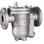
Free-floating steam trap

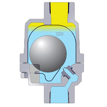
A free-floating steam trap is that the floating ball rises or falls according to the water condensation with the water level due to the principle of buoyancy, it automatically adjusts seat hole open degree of continuous discharge condensate, when water stops into the ball back to the closed position and then drainage. The drain valve seat hole is always below the condensation water form a water seal, water and gas separation without leakage of steam.


Thermostatic steam trap

This kind of steam trap is caused by the temperature difference between the steam and condensate water temperature element deformation or expansion to drive valve core open and close. The thermostatic steam trap has a large degree of undercooling, generally 15 to 40. It uses heat energy to make the valve always has high-temp condensate water and no steam leakage, has been widely used in steam pipeline, heat pipeline, heating equipment or small heating equipment with low-temperature requirements, is the most ideal type of steam trap. The type of thermo-static steam trap includes diaphragm steam trap, bellows steam trap, bimetal plate steam trap and etc.


Diaphragm steam trap

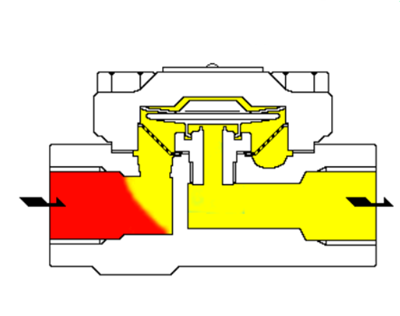
The main action element of the diaphragm trap is the metal diaphragm, of which is filled with vaporization temperature that is lower than the saturation temperature of water liquid, generally the valve temperature is lower than the saturation temperature of 15℃ or 30℃. Diaphragm trap is sensitive to response, resistance to freezing and overheating, small size and easy to install. Its backpressure rate is more than 80%, cannot condense gas, long service life and easy maintenance.


Thermal steam trap

According to the phase change principle, the thermal power steam trap by steam and condensate water through the flow rate and volume changes of different heat so that the valve plate produced different pressure difference, that drives the valve plate switch valve. It is powered by steam and loses a lot of steam. It‘s characterized by simple structure, good water-resistant. With a maximum back of 50%, noisy, valve plate work frequently and short service life. The type of thermal power steam trap includes the thermodynamic (disc) steam trap, pulse steam trap, hole plate steam trap and so on.


Thermodynamic (disc) steam trap

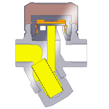
There is a movable disc in the steam trap which is both sensitive and actuating. According to the steam and condensate when the flow rate and volume of different thermodynamic principles, so that the valve plate up and down to produce different pressure differential drive valve plate switch valve. The steam leakage rate is 3%, and the undercooling degree is 8℃-15℃. When the device starts, the cooling condensate appears in the pipeline and pushes off the valve plate by the working pressure to discharge rapidly. When the condensate is discharged, the steam is then discharged, the volume and flow rate of the steam is larger than the condensates, so that the valve plate produces pressure difference to close quickly due to the suction of the steam flow rate. When the valve plate is closed by pressure on both sides, the stress area below it is less than the pressure in the steam trap chamber from the steam pressure above, the valve plate is closed tightly. When the steam in the steam trap chamber cools to condense, the pressure in the chamber disappears. Condensate by working pressure to push the valve plate, continue to discharge, circulation and intermittent drainage.

Tips for safety valve installation

The safety valve is widely used in a steam boiler, LPG tanker, oil well, high-pressure bypass, pressure pipeline, pressure vessel of steam power generation equipment, and etc. The safety valve is closed under the action of external force on the opening& closure parts and when the pressure of the medium in the equipment or pipeline exceeds the specified value, it opens and drains the medium out of the system to protect the safety of the pipeline or equipment.

The safety valve shall be installed upright and as close as possible to the protected equipment or piping. If not installed nearby, the total pressure drop between the pipe and the safety valve inlet should not exceed 3% of the valve’s constant pressure value or 1/3 of the maximum allowable open/closed pressure difference (whichever is the lesser). In engineering practice, the total pressure drop of the pipeline can be reduced by expanding the inlet diameter of the safety valve appropriately, adopting a long radius elbow and reducing the number of the elbow. Besides, what else should be considered?


  1. The safety valve shall be installed in a place convenient for maintenance and a platform shall be set up for maintenance. The large diameter safety valve should consider the possibility of lifting after the safety valve is disassembled. In engineering practice, the safety valve is often mounted on top of the piping system.
  2. The safety valve for a liquid pipeline, heat exchanger or pressure vessel, which can be installed horizontally when the pressure increases due to thermal expansion after the valve is closed; The outlet of the safety relief valve shall be free of resistance to avoid backpressure and to prevent the accumulation of solid or liquid materials.
  3. The inlet pipe of the safety valve shall have a long radius elbow with at least 5% bend. The inlet pipe should avoid u-bend as far as possible, otherwise, the condensable material at the lowest point is connected with the continuous flow drain pipe to the same pressure system, the viscous or solid condensate needs the heat tracing system. In addition, the backpressure of the outlet line shall not exceed the specified value of the relief valve. For example, the backpressure of the ordinary spring safety valve does not exceed 10% of its fixed value.
  4. The sectional area of the connecting pipe between the safety valve and the boiler pressure vessel shall not be less than that of the safety valve. The whole safety valve is installed on a joint at the same time, the cross-section area of the joint shall not be less than 1.25 times of the safety valve.
  5. The outlet pipeline of the relief valve discharged into the closed system shall be connected to the top of the relief main pipe according to the medium flow direction of 45°, so as to avoid the condensate in the main pipe flowing into the branch pipe and reduce the backpressure of the relief valve.
  6. If the outlet of the safety valve is lower than the relief pipe or the discharge pipe, it is necessary to raise the access pipe. In steam service, the safety valve shall be installed so that the condensate does not converge upstream of the disc.
  7. If a discharge line is to be installed, the inside diameter shall be greater than the outlet diameter of the relief valve. For containers of inflammable or toxic or highly toxic media, the discharge line shall be directly connected to an outdoor or safe place with treatment facilities. No valves shall be installed on the discharge line. In addition, flammable, explosive or toxic media pressure vessels must have safety devices and recovery systems. The outlet of the discharge line shall not be directed towards equipment, platforms, ladders, cables, etc.


When the safety valve cannot be mounted on the container body due to special reasons, it can be considered to be mounted on the outlet pipeline. However, the pipeline between them should avoid sudden bending and the outer diameter should be reduced, so as to avoid increasing the pipeline resistance and causing dirt accumulation and blockage. In addition, a power assist device (actuator) is used to open the safety valve when the pressure is lower than the normal set pressure. As a kind of special equipment, when selecting the safety valve, it is necessary to consider the nature of the medium, the actual working condition, the valve material and connection mode and related parameters.