The globe valve in ammonia application

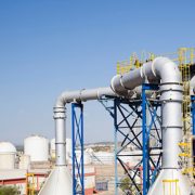
Ammonia is an important raw material for the manufacture of nitric acid, ammonium salt and amine. Ammonia is a gas at room temperature and can be liquefied under pressure. Most metals such as Stainless steel, Aluminum, Lead, Magnesium, Titanium, etc. have excellent corrosion resistance to ammonia gas, liquid ammonia and ammonia water. Cast iron and carbon steel also have good corrosion resistance to ammonia gas or liquid ammonia, the corrosion rate is generally less than 0.1mm/year, so ammonia production and storage equipment is generally made of steel from the perspective of cost.

The check valve, globe valve, ball valve, and other valves can be used in ammonia and liquid ammonia piping system. These valves bring the gas pressure down to a safe level and pass it through other valves to the service system. Among them, the most commonly used is the globe valve. Ammonia globe valve is a kind of force-sealing valve, that is, when the valve is closed, the pressure must be applied to the disc so that the sealing surface are leak-free.

When the medium enters the valve from below the disc, it is necessary to overcome the friction of the stem and packing and the pressure from the medium. The force of valve closure is greater than that of valve opening, so the diameter of the stem should be large or the stem bending. The flow of self-sealing ammonia gas globe valve is generally from top to bottom, that’s the medium into the valve cavity from the top of the disc, then under the pressure of the medium, the force of valve closing is small and the valve opening is big, the diameter of the stem can be correspondingly reduced. When the globe valve is open, when the opening height of the disc is 25% ~ 30% of the nominal diameter, the flow has reached the maximum, indicating that the valve has reached the fully open position. Therefore, the fully open position of the globe valve shall be determined by the travel of the disc. So what are the characteristics of globe valves for ammonia application?

  • Copper reacts with ammonia gas and ammonia water to form soluble complexes and produce dangerous stress corrosion cracking. In the ammonia-environment, even trace amounts of ammonia can cause stress corrosion in the atmosphere. Valves made of copper and copper alloy are generally not suitable for ammonia applications.
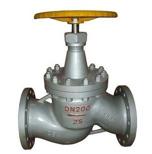
  • Ammonia globe valve is ono-rising-stem cone design compared with the common globe valve. Its sealing surface is mostly Babbitt alloy and the valve body is made of stainless steel CF8 or high-quality carbon steel WCB to be used to the maximum requirements, can be resistant to ammonia corrosion, low-temperature resistance to -40℃.
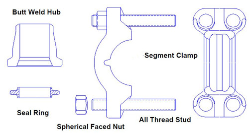
  • The tongue and groove face design of flange connection ensures reliable sealing performance even when pipeline pressure fluctuates.
  • Multi-layer PTFE (PTFE) or Babbitt alloy sealing material and a composite soft packing made of PTFE+ butanol + spring) ensure that the valve packing box is free of leakage during the service life.
  • PTFE plain gaskets, stainless steel + graphite wound gaskets, stainless steel + PTFE wound gaskets are also recommended for ammonia valves.


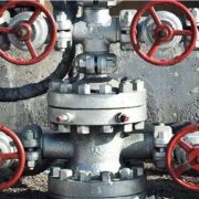
The handwheel of the ammonia globe valve is generally painted yellow to distinguish it from valves for other applications. In addition, vertical check valves and lift check valves are also available for ammonia applications. Their discs rise and fall depending on the differential pressure of the fluid and their own weight, automatically stopping the medium against the current and protecting the upstream equipment, suitable for most ammonia tank on the horizontal pipeline.


Emergency Block Valve (EBV) for Refinery plant

The emergency block valve is also known as an emergency shutdown valve (ESDV) or an emergency isolation valve (EIV). API RP 553, specification of Refinery Valves and Accessories for Control and Safety Instrumented Systems, defined emergency block valve as follows: “Emergency block valves are designed to control a hazardous incident. These are valves for emergency isolation and are designed to stop the uncontrolled release of flammable or toxic materials. Any valve in the fire zone handling flammable liquid should be fire-safe.

Generally, a metal-seated ball valve, gate valve, butterfly valve can be used as an EBV to cutting off or isolation. It is generally installed between the inlet pressure source and the regulator. When the pressure of the protected system reaches a specified value, the valve will be quickly closed, cut off or isolated to avoid the occurrence of fire, leakage and other accidents. It is suitable for gas, natural gas and liquefied petroleum gas and other combustible gas storage, transportation, etc.

The emergency block valve is installed on the inlet and outlet pipeline of the liquefied hydrocarbon spherical tank. API 2510 “design and construction of liquefied petroleum gas (LPG) facilities” provides that the block valve on the liquefied hydrocarbon pipeline shall be as close as possible to the tank body, preferably close to the tank wall pipe outlet flange for easy operation and maintenance. When a 38 m³ (10,000 gals) liquefied hydrocarbon tank is on fire for 15 min, all block valves located in the pipeline below the highest liquid level of the tank shall be able to close automatically or operate remotely. The block valve control system shall be fire-safe and manually operated. API RP2001 “oil refinery fire prevention” explicitly requires that “emergency block valves should be installed at the nozzles below the liquid level of containers containing a large amount of flammable liquid.

API RP553 specifies the basic principles of setting emergency block valves for compressors, pumps, heating furnaces, containers, etc. It is closely related to the size of the equipment volume, medium, temperature, as well as the pump power and capacity. According to the requirements and design cases, emergency cut-off valve EBV shall be installed on the exit (or inlet) line adjacent to the high fire hazard equipment and fully isolated to stop the release of flammable or toxic materials. The emergency block valve is generally required for high – fire equipment and fire zone.


High fire equipment includes:

A container larger than 7.571m (2,000 gallons);

LPG storage tanks larger than 15.5 m (4 000 gallons);

A container or heat exchanger whose internal temperature of combustible liquid exceeds 315℃ or whose temperature has exceeded spontaneous combustion;

The capacity of transporting combustible liquid such as hydrocarbon exceeds 45 m/h;

The power of the combustible gas compressor is greater than 150 kW;

A heating furnace in which combustible liquid is heated through a furnace tube;

The internal pressure is greater than 3.45mpa, and the mode is an exothermic hydrocarbon reactor.

Fire zone:

An area within 9 m horizontal or 12 m vertical from high fire hazard equipment;

The area within 9 m from the spherical tank containing combustible medium, etc.

What’s High pressure self-tightening flange (Grayloc Flange)?

High pressure self-tightening flange is a clamped connector for high pressure (1500CL-4500CL), high temperature, highly corrosive process. It is sealed by the elasticity of reusable metal ring. It is lighter than universal flange but has a better sealing effect, saving weight and space, maintenance time and cost. It is widely used in petrochemical, oil and gas exploitation, industrial gas production, petroleum refining, food processing, chemical industry, environmental engineering, mineral and nuclear power, aerospace, shipbuilding, synthetic fuel processing, coal oxidation and liquefaction and other fields. GRAYLOC connectors is recognized as the production standard for critical service piping and vessel connections.

The high pressure self -tightening flange is composed of segment clamp, butt weld hub, sealing ring and bolt. Compared with the conventional soft sealing flange, that is, plastic deformation of the gasket to achieve the seal, the high-pressure self-tightening flange depends on the hub of the seal ring (T-Arm) elastic deformation to seal, that is, the metal to metal seal. The combination of joint, clamp and sealing ring makes the strength of the joint far greater than the strength of the pipe based material. One pressed, the sealing element is sealed not only by the force exerted by the external connection, but also by the pressure of the medium itself. The higher the medium pressure is, the greater the compression force is exerted on the sealing element.

Metal sealing ring: The sealing ring is the core part of the high pressure self-tightening flange, and its cross section is approximately in the shape of “T”. The sealing ring is clamped by the end face of two sets of hub to form a whole with the base tube, which greatly improves the strength of the connecting parts. The two arms of the “T” shaped section, that’s sealing lip, which generates an internal conical surface of the sealing area with the socket, which extends freely to form the sealing under the action of external forces (within the yield limit).

Hub:After the two hub joints are clamped, the force is exerted on the sealing ring and the sealing lip deviates from the inner sealing surface of the hub. Such deviating elasticity returns the load of the sealing surface inside the hub back to the lip of the sealing ring, forming a self-enhanced elastic seal.

Clamp:The clamp can be adjusted freely in 360° direction for easy installation.

Spherical faced nut/bolt:Generally, each set of high pressure self-tightening flange only needs four sets of high pressure spherical bolts to achieve the overall strength.


The feature of a high-pressure self-tightening flange

  • Good tensile strength: In most cases, the high pressure self-tightening flange in the connection can withstand the tensile load better than the pipe itself. The destructive test proves that the flange is still intact without leakage after the failure of the pipe under tensile load.
  • Good corrosion resistance: Different flange materials can fulfill the special corrosion protection requirements of different environments.
  • Good bending resistance: A large number of tests show that this flange will not leak or loosen when it is under a large bending load. The actual tests show that the DN15 high-pressure self-tightening flange has been subjected to many cold bends in the pipeline, and its joints have no leakage and not loose.
  • Good compression resistance: The high-pressure self-tightening flange will not bear overload compression in the normal pipeline; The maximum load of the flange at higher compression loads is determined by the ultimate strength of the pipe.
  • Good impact resistance: Small size, compact structure, can withstand the impact that traditional high pressure flange can’t withstand; The metal – to – metal seal greatly enhances its impact resistance.

More information, do not hesitate to contact Perfect-valve now!

The flow rate of common medium through a valve

Valve flow and flow rate mainly depend on the valve size, structure, pressure, temperature and medium concentration, resistance and other factors. The flow and flow rate is interdependent, under the condition of a constant flow value when the flow rate increase, the valve port area is small and the resistance of the medium is large, leading to the valve is easy to damage. A large flow rate will produce static electricity to flammable and explosive media; However, a low flow rate means low production efficiency. It is recommended to choose a low flow rate (0.1-2 m/s) according to the concentration for large and explosive media such as oil.

The purpose of the flow rate controlling in the valve r is mainly to prevent the generation of static electricity, which depends on the critical temperature and pressure, the density, physical properties of the medium. In general, knowing the flow and flow rate of the valve, you can calculate the nominal size of the valve. Valve size is the same structure, fluid resistance is not the same. Under the same conditions, the greater the resistance coefficient of the valve, the more the flow rate through the valve and the lower the flow rate; The smaller the drag coefficient, the less the flow rate flow through the valve. Here is the flow rate of some common medium through the valve for your reference.

Medium Type Conditions Flow velocity, m/s
Steam Saturated vapor DN > 200 30~40
DN=200~100 25~35
DN < 100 15~30
Superheated steam DN > 200 40~60
DN=200~100 30~50
DN < 100 20~40
Low-pressure steam P<1.0(Absolute pressure) 15~20
Medium pressure steam P=1.0~4.0 20~40
High-pressure steam P=4.0~12.0 40~60
Gas Compressed gas(Gage pressure) Vacuum 5~10
P≤0.3 8~12
Ρ=0.3~0.6 10~20
Ρ=0.6~1.0 10~15
Ρ=1.0~2.0 8~12
Ρ=2.0~3.0 3~6
Ρ=3.0~30.0 0.5~3
Oxygen(Gage pressure) Ρ=0~0.05 5~10
Ρ=0.05~0.6 7~8
Ρ=0.6~1.0 4~6
Ρ=1.0~2.0 4~5
Ρ=2.0~3.0 3~4
Coal gas   2.5~15
Mond gas(Gage pressure) Ρ=0.1~0.15 10~15
Natural gas   30
Nitrogen gas(Absolute pressure) Vacuum/Ρ=5~10 15~25
Ammonia gas(Gage pressure) Ρ<0.3 8~15
Ρ<0.6 10~20
Ρ≤2 3~8
Other medium Acetylene Gas P<0.01 3~4
P<0.15 4~8
P<2.5 5
Chloride Gas 10~25
Liquid 1.6
 Chlorine hydride Gas 20
Liquid 1.5
liquid ammonia (Gage pressure) Vacuum 0.05~0.3
Ρ≤0.6 0.3~0.8
Ρ≤2.0 0.8~1.5
Sodium hydroxide (Concentration) 0~30% 2
30%~50% 1.5
50%~73% 1.2
Sulfuric acid 88%~100% 1.2
hydrochloric acid / 1.5
 

Water

Low viscosity water (Gage pressure) Ρ=0.1~0.3 0.5~2
Ρ≤1.0 0.5~3
Ρ≤8.0 2~3
Ρ≤20~30 2~3.5
Heating network circulating water 0.3~1
Condensate water Self-flow 0.2~0.5
Seawater, slightly alkaline water Ρ<0.6 1.5~2.5


The Flow resistance coefficient and pressure loss for valve

Valve resistance and pressure loss are different but they are so closely related, to understand their relationship, you must first understand the coefficient of resistance and the coefficient of pressure loss. Flow resistance coefficient depends on different flow structure, valve opening and medium flow rate, is a variable value. Generally speaking, fixed structure of the valve in a certain degree of opening is a fixed flow coefficient, you can calculate the valve inlet and outlet pressure according to the flow coefficient, this is the pressure loss.

The flow coefficient (discharge coefficient) is an important index to measure the flow capacity of the valve. It represents the flow rate when the fluid is lost per unit pressure through the valve. The higher the value is, the smaller the pressure loss when the fluid flows through the valve is. Most valve manufacturers include the flow coefficient values of valves of different pressure classes, types and nominal sizes in their product specifications for design and use. The value of the flow coefficient varies with the size, form and structure of the valve. In addition, the flow coefficient of the valve is also affected by the valve opening. According to different units, the flow coefficient has several different codes and quantitative values, among which the most common are:


  • Flow coefficient Cv: Flow rate at 1psi pressure drop when water flows through the valve at 15.6 ° c (60 ° f).
  • Flow coefficient Kv: The volume flow rate when the water flow between 5 ℃ and 40℃ generates a pressure drop of 1bar through the valve.

Cv=1.167Kv

The Cv value of each valve is determined by the cross-section of the solid flow.

Valve resistance coefficient refers to the fluid through the valve fluid resistance loss, which is indicated by the pressure drop (Differential Pressure △P) before and after the valve. Valve resistance coefficient depends on the size of the valve, the structure and the shape of the cavity, more depends on the disc, seat structure. Each element in the valve body chamber can be considered a system of components (fluid turning, expanding, shrinking, returning, etc.) that generate resistance. So the pressure loss in the valve is approximately equal to the sum of the pressure loss of the valve components. In general, the following circumstances can be increased valve resistance coefficient.

  • The valve port is suddenly enlarged. When the port is suddenly enlarged, the velocity of the fluid part is consumed in the formation of eddy current, stirring and heating of the fluid, etc.;
  • The gradual expansion of the valve port: When the expansion Angle is less than 40 °, the resistance coefficient of the gradually expanding round tube is smaller than that of the sudden expansion, but when the expansion Angle is more than 50°, the resistance coefficient increases by 15% ~ 20% compared with the sudden expansion.
  • The valve port suddenly Narrows.
  • The valve port smooth and even turn or corner turn.
  • Symmetrical tapered connection of valve port.


In general, full-bore ball valves and gate valves have the least fluid resistance due to no turning and reducing, almost the same as the piping system, which is the valve type that offers the most excellent flow capacity.


Self-actuated regulator VS Relief Valve

Both the relief valve and the self-operated regulator are regulated by the pressure of the medium itself. The relief valve is controlled by the spring and the pressure area of the valve core corresponding to a relatively stable pressure, on the basis of the installation of a pilot pressure pipe in the valve head cylinder can adjust accurately the before and after valve pressure, that is, the self-operated regulator. Is there any difference between the self-actuated regulator and a relief valve?

  1. Different purpose. The self-operated regulator is intended to regulate while the relief valve is only for pressure reduction. The self-operated regulator is mainly to maintain the stability of pressure and pressure reducing valve is mainly to reduce the pressure to a safe value;
  2. The pressure reducing valve can be adjusted to the pressure manually. If the pressure in front of the valve changes greatly, frequent adjustment is needed. The self-operated control valve is automatic according to a set, objective value, the pressure can be constant after adjustment; If the pressure before and after the valve changes at the same time, the relief valve cannot automatically adjust to the fixed pressure, while the self-operated regulator can automatically maintain the back pressure or the pressure before the valve stable;
  3. The self-operated regulating valve can not only regulate the pressure before and after the valve but also control the differential pressure, temperature, liquid level, flow rate, etc. The relief valve can reduce the pressure after the valve only, single function;
  4. The adjusting accuracy of the relief valve is higher, generally 0.5, and the self-operated regulator is generally 8-10%;
  5. Different application. The self-operated regulator is widely used in petroleum, chemical industry and other industries. The relief valve is mainly used in water supply, fire control, heating and central air conditioning systems.

Generally speaking, the self-operated regulator is mainly used in the pipeline below DN80 and the pneumatic regulating valve is larger for pipe diameter. Relief valve needs to be equipped with a fixed set of valves because it is easy to leak, that is, the globe valve and the connecting valve are installed for maintenance and debugging at both ends of the control valve, and the relief valve and pressure gauge shall be set after pressure reducing.