What’s sluice gate valve?

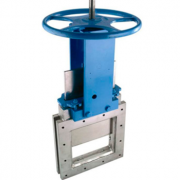
Similar with the knife gate valve in shape, the sluice gate valve is a type of manually screw operated gate, also known as a sluice gate valve. The sluice gate valve is mainly composed of frame, gate, screw, nut and other parts used for slurry and abrasive fluid systems. By turning the handwheel, the screw drives the screw nut and gate reciprocating along the horizontal direction to realize the opening and closing of the gate. Its installation is not limited by the Angle, easy to operate, but also to choose an actuator according to customer needs such as pneumatic, electric and so on. General installation flange on both sides can achieve different sizes of pipe installation.

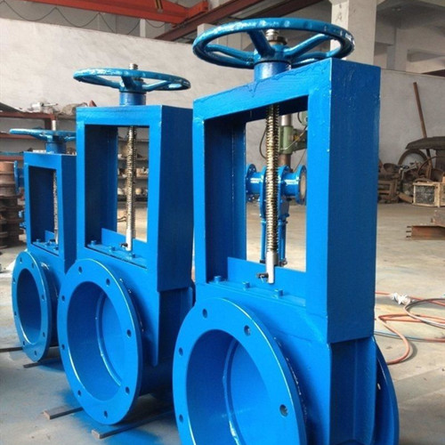
Flange manual sluice gate valve is often used with an unloading device or hopper, generally a square sluice gate valve and circular sluice gate valve according to the shape of the inlet and outlet. Manual sluice gate valve is characterized by advantages of simple structure, reliable sealing, flexible operation, wear resistance, smooth passage, easy installation and disassembly. It is especially suitable for the transportation and flow regulation of water, slurry, powder, solid materials and block/lump materials less than 10mm, has been widely used in pulp and paper, cement industry, mining and food industry. It is an ideal device for where large changes in the control volume, frequent startup/shutdown, and rapid operation are required.


The installation tips of sluice gate valve

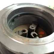
  1. Check the valve chamber and sealing surface, and no dirt or sand is allowed before installation;
  2. Flange bolt connection shall be tightened evenly;
  3. The packing part shall be pressed to ensure the sealing property of the packing and flexible opening of the gate;
  4. Check the valve model, connection size and medium flow direction before installation to ensure that they are consistent with the requirements reserve the necessary space for the valve actuator;


The common specification of sluice gate valve

Type A×A B×B C×C H L n-d Weight
One-way 200×200 256×256 296×296 820 100 8-Φ12 62
250×250 306×306 346×346 930 100 8-Φ14 70.5
300×300 356×356 396×396 1050 100 8-Φ14 81
400×400 456×456 496×496 140 100 12-Φ14 114
450×450 510×510 556×556 1450 120 12-Φ18 130
500×500 560×560 606×606 1610 120 16-Φ18 147
Two -way


600×600 660×660 706×706 1830 120 16-Φ18 169
700×700 770×770 820×820 2130 140 20-Φ18 236
800×800 870×870 920×920 2440 140 20-Φ18 303
900×900 974×974 1030×1030 2660 160 27-Φ23 424
1000×1000 1074×1074 1130×1130 2870 160 24-Φ23 636


More details about the sluice gate valve and knife gate valve, contact us now!

Types of check valve

The check valve is a kind of valve that depends on the medium flow itself to open and close automatically to prevent the reverse flow, also known as the reverse valve, one-way valve, non-return valve(NRV) and backpressure valve. The purpose of the check valve is to prevent reverse flow of the medium, to prevent the pump and drive motor from reversing, and to prevent the release of the container medium. When the fluid flows in the specified direction, the pressure of the fluid causes the disc to open, but when the fluid flows in the opposite direction, the pressure of the fluid and the self-aligning disc work together on the seat to prevent backflow, and can also be used to supply the auxiliary system where the pressure may rise above the system pressure. According to the structure, the check valve can be divided into swing check valve, wafer check valve, lift check valve, vertical check valve, double check valve, butterfly check valve, ball type check valve, Y type check valve.


Swing check valve

Swing check valves are divided into single-disc, double-disc and multi-disc check valves. The round disc around the seat axis moves for rotary, flow resistance is small because of the streamlined valve inside the channel, suitable for low flow rate and flow is not often changed in large-caliber pipeline. To ensure that the disc reaches the seat face in the proper position each time, the disc is designed in a hinged mechanism so that the disc has sufficient swing space and is in full contact with the seat. The disc may be made entirely of metal, may be covered with leather and rubber, or made by cladding cover, that depending on performance requirements.


Lift Check Valves

Lifting check valve can be divided into vertical and straight through according to the structure. The lift check valve disc is located on the seat sealing face, similar to the globe valve, the fluid pressure causes the disc to rise from the seat sealing face, the medium backflow causes the disc to fall back to the seat and cut off the flow. A vertical lift check valve is generally used in a nominal 50mm horizontal pipe. Straight-through lift check valves can be installed in both horizontal and vertical pipelines. The bottom valve is generally only installed on the vertical pipe at the sump pump, and the medium flows from bottom to top. The sealing performance of lift check valve is better than that of swing check valve.


Butterfly check valve

Also known as the wafer check valve, generally, straight through, the butterfly check valve is suitable for low pressure, large diameter and installation are limited occasions. Because the butterfly check valve’s working pressure is not high, generally below 6.4mpa, but the nominal diameter can reach more than 2000mm.The installation position of the wafer type check valve is not restricted. It can be on the horizontal pipeline, or on the vertical or on the inclined pipeline.


Diaphragm check valve
The diaphragm check valve is suitable for pipeline that easy to produce water hammer, the diaphragm can be very good to eliminate the water hammer effect when the medium countercurrent. Limited by the material of diaphragm, the diaphragm check valve is generally used in low-pressure normal temperature pipelines, especially in the water pipeline. The working temperature of the medium is -20 ~ 120℃ and the working pressure is less than 1.6mpa, and the diameter can reach up to 2000mm. Due to its excellent waterproof performance, simple structure and low manufacturing cost, it has been widely used in recent years.


The overlay welding(hardfacing) for valve sealing

Sealing surface is the key part of the valve, in the sealing surface surfacing welding a layer of a special alloy, that is, hard facing or overlaying, can improve the hardness of the valve sealing surface, wear resistance and corrosion resistance, reduce the cost, and improve the service life of the valve. The quality of the sealing surface directly affects the service life of valve. Choosing the material of the sealing surface reasonably is one of the important ways to improve the service life of the valve. If you want to obtain the required valve surfacing surface, it is necessary to select the appropriate base material (workpiece material) and welding method in strict accordance with the operating instructions and operating requirements.


Commonly used overlay welding alloys include cobalt-based alloys, nickel-based alloys, iron-based alloys and copper-based alloys. Cobalt-based alloy is most used in valves because of its good high-temperature performance, excellent thermal strength, wear resistance, corrosion resistance and heat resistance fatigue performance than that of iron or nickel-based alloy. These alloys can be made into the electrode, wire (including flux-cored wire), flux (transition alloy flux) and alloy powder, etc., using the methods like submerged arc automatic welding, manual arc welding, tungsten argon arc welding, plasma arc welding, oxygen-acetylene flame welding in all kinds of valve shell and sealing surface. The welding groove is shown in the following figure:

The materials used for overlay welding the valve sealing surface are electrode, welding wire or alloy powder, etc., which are generally selected according to the valve’s operating temperature, working pressure and corrosive medium, or the type of valve, sealing surface structure, sealing pressure and allowable pressure, or enterprise processing capacity and user requirements. Each valve is open and closed under different operating parameters, so different temperature, pressure, medium and valve sealing surface material has different requirements. The experimental results show that the wear resistance of the valve sealing surface material is determined by the structure of the metal material. Some metal materials with austenitic matrix and a small amount of hard structure have low hardness but good wear resistance. Valve sealing surface has a certain high hardness is to avoid hard sundries in the medium pad and scratch. Considering comprehensively, the hardness value HRC35~ 45 is appropriate.


Valve sealing surface and failure reasons:

Valve type Overlay  welding part Sealing surface type Failure reasons
Gate valve Seat, gate The plane face Abrasion – based, erosion
Check valve Seat, disc The plane face Impact and erosion
High-temp ball valve Seat pyramidal face Abrasion – based, erosion
Butterfly valve Seat pyramidal face Erosion
Globe valve Seat, disc Plane or pyramidal Erosion – based, abrasion
Pressure reducing valve Seat, disc Plane or pyramidal Impact and erosion


Due to the uneven temperature distribution of welds and the thermal expansion and cold contraction of weld metal, residual stress is inevitable during overlay welding. In order to relax the welding residual stress, stabilize the shape and size of the structure, reduce distortion, improve the performance of the base material and welded joints, further release of harmful gases in the weld metal especially hydrogen to prevent delayed cracking, heat treatment after overlay welding is necessary. Generally speaking, the transition layer to 550℃ low-temperature stress treatment and time depends on the base wall thickness. In addition, the carbide alloy layer requires low-temperature stress-free heat treatment at 650℃, with heating speed less than 80℃/h and cooling speed less than 100℃/h. After cooling to 200℃, cool slowly to room temperature.