The commonly used material for valve body

Meets the preceding text, the common material of valve body includes carbon steel, low-temperature carbon steel, alloy steel, Austenitic stainless steel, cast copper-alloy titanium alloy, aluminum alloy, etc., of which carbon steel is the most widely used body material. Today here we will collect the commonly used material for valve body.

Valve body material Standards Temperature /℃ Pressure /MPa Medium
Gray cast iron -15~200 ≤1.6 Water, gas,


Black malleable iron -15~300 ≤2.5 Water, seawater, gas, ammonia


Ductile iron -30~350 ≤4.0 Water, seawater, gas, air, steam


Carbon steel (WCA、WCB、WCC) ASTM A216 -29~425 ≤32.0 Non-corrosive applications, including water, oil and gas
Low-temp carbon steel (LCB、LCC) ASTM A352 -46~345 ≤32.0 Low temp application
Alloy steel (WC6、WC9)

(C5、C12)

ASTM A217 -29~595

-29~650

High-pressure Non-corrosive medium /

Corrosive medium

Austenitic stainless steel ASTM A351 -196~600 Corrosive medium
Monel alloy ASTM A494 400 Medium containing hydrofluoric acid
Hastelloy ASTM A494 649 Strong corrosive media such as dilute sulfuric acid
Titanium alloy A variety of highly corrosive media
Cast copper alloy -273~200 Oxygen, seawater
Plastics and ceramics ~60 ≤1.6 Corrosive medium


Codes Material Standards Applications Temperature
WCB Carbon steel ASTM A216 Non-corrosive applications, including water, oil and gas -29℃~+425℃
LCB Low-temp steel ASTM A352 Low temp application -46℃~+345℃
LC3 3.5%Ni- steel ASTM A352 Low temp application -101℃~+340℃
WC6 1.25%Cr0.5%Mo steel ASTM A217 Non-corrosive applications, including water, oil and gas -30℃~+593℃
WC9 2.25Cr
C5 5%Cr 0.5%Mo ASTM A217 Mild or noncorrosive applications -30℃~+649℃
C12 9%Cr 1%Mo
CA15(4) 12%Cr steel ASTM A217 Corrosive applications +704℃
CA6NM(4) 12%Cr steel ASTM A487 Corrosive applications -30℃~+482℃
CF8M 316SS ASTM A351 Corrosive, ultra-low or high temp non-corrosive applications -268℃ to+649℃,425℃ above or specified carbon content is 0.04% or above
CF8C 347SS ASTM A351 High temp,corrosive applications -268℃to+649℃,540℃ above or specified carbon content is 0.04% or above
CF8 304SS ASTM A351 Corrosive, ultra-low or high temp non-corrosive applications -268℃to+649℃,425℃  above or specified carbon content is 0.04% or above
CF3 304LSS ASTM A351 Corrosive or non-corrosive applications +425℃
CF3M 316LSS ASTM A351 Corrosive or non-corrosive applications +454℃
CN7M Alloy stel ASTM A351 Good corrosion resistance to heat sulfuric acid +425℃
M35-1 Monel ASTM A494 Weldable grade, good resistance to organic acid and saltwater corrosion.

Most alkaline solution corrosion resistance

+400℃
N7M Hastelloy B ASTM A494 Suitable for various concentrations and temperatures of hydrofluoric acid, good resistance to sulfuric acid and phosphoric acid corrosion performance +649℃
CW6M Hastelloy C ASTM A494 At high temperature, it has high corrosion resistance to formic acid, phosphoric acid, sulfurous acid and sulfuric acid +649℃
CY40 Inconel ASTM A494 Works well in high temp applications, has good corrosion resistance to highly corrosive fluid media


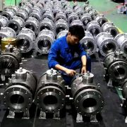
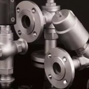
As a fully stocked manufacturer and distributor of the industrial valve, PERFECT provides a complete line of valves for sale that is supplied to various industries. Available valve body material including carbon steel, stainless steel, titanium alloy, copper alloys, etc and we make the material easy to find for your valve need.


Control valve seat leakage class

In past articles, we introduce “What caused the leakage of valve” and “The leak rates standards of the industrial valve”, today here we will continue to discuss the valve leakage class and classification.

ANSI FCI 70-2 is an industry standard for control valve seat leakage, specified six leakage classes (Class I, II, III, IV, V, VI) for control valves and defines the test procedure, and superseding ANSI B16.104. The most commonly used are CLASS I, CLASS IV and CLASS Vl. Metal-elastic seal or metal seal should be selected in engineering design according to the characteristics of the medium and the opening frequency of the valve. Metal seated valve seal grades should be is stipulated in the order contract, the rates I, Ⅱ, Ⅲ is used less due to request a lower level, generally choose Ⅳat least and V or Ⅵ for higher requirements.


Classifications of control valve seat (ANSI/FCI 70-2 and IEC 60534-4)

Leakage class Maximum leakage allowable Test medium Test pressure Test rating procedures Valve type
Class I / / / No test required Metal or resilient seated valves
Class II 0.5% of rated capacity Air or water at 50-125 F (10-52C) 3.5 bar, operating differential whichever is lower Lower of 45 to 60 psig or maximum operating differential Commercial double-seat control valves or balanced single-seat control valves with a piston ring seal and metal-to-metal seats.
Class III 0.1% of rated capacity As above As above As above Same as class II, but a higher degree of seat and seal tightness.
Class IV 0.01% of rated capacity As above As above As above Commercial unbalanced single-seat control valves and balanced single-seat control valves with extra tight piston rings or other sealing means and metal-to-metal seats.
Class V 0.0005 ml per minute of water per inch of port diameter per psi differential Water at 50-125F (10-52C) Max service pressure drop across valve plug, not to exceed ANSI body rating. Maximum service pressure across valve plug not to exceed ANSI rating Metal seat, unbalanced single-seat control valves or balanced single-seat designs with exceptional seat and seal tightness
Class VI Not to exceed amounts shown in following table based on port diameter. Air or nitrogen at 50-125 F (10-52C) 3.5 bar(50 psig) or max rated differential pressure across valve plug whichever is lower. Maximum service pressure across valve plug not to exceed ANSI rating Resilient seating control valves either unbalanced or balanced single-seat with “O” rings or similar gapless seals.


What caused the leakage of valve?

Valves are one of the main leakage sources in the pipeline system of the petrochemical industry, so it’s critical to the leakage of valves. Valve leakage rates are actually the valve sealing level, valve sealing performance is referred to as the valve sealing parts to prevent the ability of media leakage.

The main sealing parts of the valve including the contact surface between the opening and closing parts and the seat, the fitting of packing and stem and packing box, the connection between the valve body and the bonnets. The former belongs to internal leakage, which directly affects the ability of the valve to cut off the medium and the normal operation of the equipment. The last two are external leakage, that is, media leakage from the inner valve. The loss and environmental pollution caused by external leakage are often more serious than that caused by internal leakage. Then do you know what caused the valve leakage?

Casting and forging valve body

The quality defects formed in the casting process such as sand holes, sand, slag holes and pores, and the forging quality defects like cracks and folds, both can cause leakage in the valve body.

Packing

The sealing of the stem part is the packing in the valve, that is designed to prevent gas, liquid and other media leakage. valve leakage will be caused by the deflection of gland fastening, improper packing bolt fastening, too little packing, wrong packing material and improper packing installation method in the installation process of packing.

Sealing ring

Incorrect or inappropriate seal ring material, poor surfacing welding quality with body; loose thread, screw and pressure ring; seal ring mounting, or use of a defective seal ring that was not found in the pressure test, resulting in valve leakage.

Sealing surface

Rough grinding of sealing surface, deviation of assembly of valve stem and closing part, improper quality selection of sealing surface material will cause leakage of the contact part between the sealing surface and valve stem.


In general, external leakage of valves is mainly caused by the poor quality or improper installation of the cast body, flange, and packing. Internal leakage often occurs in three parts: open and close parts and seat sealing surface of the joint, valve body and bonnet joint, valve closed position.

In addition, improper valve types, medium temperature, flow, pressure, or valve switch can not be fully closed, which will also cause valve leakage. Valve leakage is not allowed especially for high temperature and pressure condition, flammable, explosive, toxic or corrosive media, so the valve must provide reliable sealing performance to meet the requirements of its use conditions on the leakage.

How to prevent valve cavitation?

The disc and seat and other parts of the internal of the control valve and the reducing valve will appear friction, groove and other defects, most of these are caused by cavitation. Cavitation is the whole process of bubble accumulation, movement, division and elimination. When the liquid passes through the valve partially open, the static pressure is less than the saturation pressure of the liquid in the area of increasing velocity or after the valve is closed. At this time, the liquid in the low-pressure area begins to vaporize and produces small bubbles that absorb impurities in the liquid. When the bubble is carried to the area of higher static pressure by the liquid flow again, the bubble suddenly bursts or explodes, we call this kind of hydraulic flow phenomenon valve cavitation.

The direct cause of cavitation is flashing caused by a sudden change of resistance. Flashing refers to the high pressure of the saturated liquid after decompression into a part of the saturated steam and saturated liquid, bubble and the formation of smooth friction on the surface of the parts.

When the bubbles burst during cavitation, the impact pressure can be up to 2000Mpa, which greatly exceeds the fatigue failure limit of most metal materials. Bubble rupture is the main source of noise, the vibration produced by it can produce up to 10KHZ of noise, the more bubbles, the noise is more serious, in addition, cavitation will reduce the bearing capacity of the valve, damage valve inner parts and prone to produce leakage, then how to prevent valve cavitation?


  • Multiple-stage pressure reducing

Multistage step-down internal parts, that is, the pressure drop through the valve into several smaller, so that the pressure vena contraction section is greater than the steam pressure, to avoid the formation of steam bubbles and eliminate cavitation.


  • Increase the hardness of the material

One of the main causes of valve damage is that the material hardness can not resist the impact force released by the bubble burst. Surfacing or spray welding of stryker alloy based on the stainless steel to form a hardened surface, once damaged, a second time surfacing or spray welding can extend its service life of the equipment and reduce the maintenance cost.


  • Porous throttling design

Special seat and disc structure make the flow of liquid pressure higher than the saturated vapor pressure, the concentration of injection liquid in the valve of the kinetic energy into heat energy, thus reducing the formation of air bubbles.

On the other hand, making the bubble burst in the center of the sleeve to avoid the damage directly on the surface of the seat and disc.


How to choose valve for oxygen pipeline?

Oxygen has typically active chemical properties. It is a strong oxidizing and a combustibility substance and can combine with most elements to form oxides except for gold, silver and inert gases such as helium, neon, argon and krypton. An explosion occurs when oxygen is mixed with combustible gases (acetylene, hydrogen, methane, etc.) in a certain proportion or when the pipe valve meets a sudden fire. The oxygen flow in the pipeline system change in the process of oxygen gas transportation, the European Industrial Gas Association (EIGA) developed the standard IGC Doc 13/12E “Oxygen Pipeline and Piping Systems” divided the Oxygen working conditions for “impact” and “non-impact”. The “impact ” is a dangerous occasion because it is easy to stimulate energy, causing combustion and explosion. The oxygen valve is the typical “impact occasion”.

Oxygen valve is a type of special valve designed for oxygen pipeline, has been widely used in metallurgy, petroleum, chemical and other industries involving oxygen. The material of the oxygen valve is limited to working pressure and flow rate to prevent the collision of particles and impurities in the pipeline. Therefore, the engineer should fully consider friction, static electricity, non-metal ignition, possible pollutants (carbon steel surface corrosion) and other factors when selecting oxygen valve.

Why are oxygen valves prone to explode?

  • The rust, dust and welding slag in the pipe cause combustion by friction with the valve.

In the process of transportation, the compressed oxygen will rub and collide with oil, iron oxide scrap or small particle combustor (coal powder, carbon particle or organic fiber), resulting in a large amount of friction heat, resulting in the combustion of pipes and equipment, which is related to the type of impurities, particle size and airflow speed. Iron powder is easy to combust with oxygen, and the finer the particle size, the lower the ignition point; The greater the velocity, the easier it is to burn.

  • Adiabatically compressed oxygen can ignite combustibles.

The low ignition point materials like oil, rubber in the valve will ignite at a local high temperature. The metal reacts in oxygen, and this oxidation reaction is significantly intensified by increasing the purity and pressure of oxygen. For example, in front of the valve is 15MPa, the temperature is 20℃, the pressure behind the valve is 0.1MPa, if the valve is opened quickly, the oxygen temperature after the valve can reach 553℃ according to the calculation of adiabatic compression formula, which has reached or exceeded the ignition point of some materials.

  • The low ignition point of combustibles in high-pressure pure oxygen is the inducement of oxygen valve combustion

The intensity of the oxidation reaction depends on the concentration and pressure of oxygen. The oxidation reaction occurs violently in the pure oxygen, at the same time gives off a large amount of heat, so the oxygen valve in the high-pressure pure oxygen has great potential danger. Tests have shown that the detonation energy of fire is inversely proportional to the square of the pressure, which poses a great threat to the oxygen valve.

The pipes, valve fittings, gaskets and all materials in contact with oxygen in pipelines must be strictly cleaned due to the special properties of oxygen, purged and degreased prior to installation to prevent scrap iron, grease, dust and very small solid particles from being produced or left behind in the manufacturing process. When they are in the oxygen through the valve, easy to cause friction combustion or explosion risk.

How to choose a valve used for oxygen?

Some projects explicitly prohibit gate valves from being used in oxygen pipelines with design pressure greater than 0.1mpa. This is because the sealing surface of gate valves will be damaged by friction in relative motion (i.e. the opening/closing of the valve), which causes small “iron powder particles” to fall off from the sealing surface and easily catch fire. Similarly, the oxygen line of another type of valves will also explode at the moment when the pressure difference between the two sides of the valve is large and the valve opens quickly.

  • Valve type

The valve installed in the oxygen pipeline is generally a globe valve, the general flow direction of the valve medium is down in and out, while the oxygen valve is the opposite to ensure a good stem force and the rapid closing of the valve core.

  • Valve material

Valve body: It is recommended to use stainless steel under 3MPa; Inconel 625 or Monel 400 alloy steel is used above 3MPa.

  • Trim

(1) The valve inner parts shall be treated with Inconel 625 and surface hardening;

(2) Valve stem/sleeve material is Inconel X-750 or Inconel 718;

(3) Should be non-reducing valve and keep the same caliber with the original pipe; Valve core seat is not suitable for hard surfacing welding;

(4) The material of the valve sealing ring is non-grease molded graphite (low carbon content);

(5) Double packing is used for the upper valve cover. The packing is high temperature resistant grease-free graphite (468℃).

(6) Oxygen in the flow of burrs or grooves will produce high-speed friction, which produces the accumulation of a large amount of heat and may explode with carbon compounds, the valve inner surface finish should meet the requirements of ISO 8051-1 Sa2.


More information about the oxygen valve, contact us now!