Why is the anti-static design essential for ball valve?

Static electricity is a common physical phenomenon. When two different materials friction, the transfer of electrons produces electrostatic charge, this process is called friction electrification. In theory, two objects of different materials can produce static electricity when they rub together, but two objects of the same material cannot. When the phenomenon produced in the valve body, that is, the friction between the ball and the non-metal seat ball, stem, and body will produce static charges when the valve is open and closed, which brings a potential fire hazard for the entire pipeline system. To avoid static sparkle, an antistatic device is designed on the valve to reduce or derive the static charge from the ball.

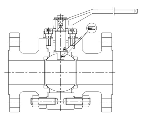
API 6D-2014 “5.23 anti-static device” stipulates as follows: “soft seated ball valve, plug valve and gate valve shall have an anti-static device. The test of the device shall be carried out in accordance with section H.5 if the buyer requires. API 6D “H.5 antistatic test” states: “resistance between the shutoff and valve body, stem/shaft and valve body shall be tested by DC power supply not exceeding 12V. Resistance measurements should be in dry before pressure test valve, its resistance value is not more than 10 Ω. Soft seated valves should install an anti-static device but metal seated valves are not required because soft plastic seats like (PTFE, PPL, NYLON, DEVLON, PEEK, etc.) tend to generate static electricity when rubbing with the ball (usually metal), while metal-metal seals do not. If the medium is flammable and explosive, the electrostatic spark is likely to cause combustion or even explosion, so connect the metal parts in contact with non-metallic through the antistatic device to the stem and body, and finally release the static electricity through the antistatic bonding device on the body. The anti-static principle of the floating ball valve is shown in the figure below.

The antistatic device consists of a spring and a steel ball (” electrostatic – spring sets”). Generally speaking, floating ball valves consist of two “electrostatic spring sets”, one is on the contact surface of the stem and ball and the other is of the stem and body. When the valve is open or closed, static electricity is generated by friction between the ball and the seat. Because of the clearance between stem and ball, when valve stem is driven by sphere, the small ball of “electrostatic spring sets” bounce, which driven the electrostatic to the valve stem, at the same time, the valve stem and valve body contact surface of the electrostatic-spring sets, will export static to the body due to the same principle, will eventually electrostatic discharge completely.

In short, an anti-static device used in a ball valve is to reduce the static charge generated on the ball due to friction. It is used to protect the valve against spark that may ignite the fuel flowing through the valve. The ball valve with an anti-static design is especially for the field like oil and gas, chemical, power plant and other industrial that fire-free is the important guarantee of safe production.

What is the difference between a relief valve and safety valve?

Safety valves and relief valves have similar structure and performance, both of which discharge internal media automatically when the pressure exceeds the set value to ensure the safety of the production device. Because of this essential similarity, the two are often confused and their differences are often overlooked as they are interchangeable in some production facilities. For a clearer definition, please refer to the ASME boiler and pressure vessel specifications.

Safety Valve: An automatic pressure control device driven by the static pressure of the medium in front of the valve is used for gas or steam applications, with full open action.

Relief Valve: Also known as the overflow valve, an automatic pressure relief device driven by the static pressure in front of the valve. It opens proportionally as the pressure exceeds the opening force, mainly used for fluid applications.


The basic difference in their operating principle: The safety valve relieves the pressure into the atmosphere i.e. out of the system, it can be a pressure relief device of fluid vessels, when the set pressure value reached then the valve opens almost fully. On the contrary, relief valve relieves the pressure by relieving the fluid back into the system, that’s the low-pressure side. Relief valve opens gradually if the pressure increased gradually.

The difference is also generally shown in capacity and setpoint. A relief valve is used to relieve pressure to prevent an overpressure condition, the operator may be needed to assist in opening the valve in response to a control signal and close back once it relieves the excess pressures and continues to operate normally.

A safety valve can be used to relieve the pressure that does not need a manual reset. For example, a thermal relief valve is used to bleed off pressure in a heat exchanger if it is isolated but the possibility of thermal expansion of the fluid could cause overpressure conditions. The safety valve on a boiler or other types of fired pressure vessels must be capable of removing more energy that is possible to be put into the vessel.

In short, Safety valves and relief valves are the two most commonly used types of control valves. The safety valve belongs to the pressure release device, which can only operate when the working pressure exceeds the allowable range to protect the system. The relief valve can make the high-pressure medium quickly to meet the pressure requirements of the system and its working process is continuous.

Nitrogen blanketing system for storage tanks

Nitrogen blanketing system is complete of devices to maintain a constant pressure state by injecting N2 gas, that is, inert gas to the upper room of the tank storage. It is composed of a series of Nitrogen high pressure reducing valve (supplying valves/bleeding valves), breather valves, pressure gage and other piping system and safety device, it can work smoothly without external energy like electricity or gas, featured the advantages of simple, convenient and economical, easy to maintain. Nitrogen blanketing system prevents any vacuum from development and reduces the evaporation, which maintains the storage tank to a designed pressure value, has been wildly used in the storage tanks, reactors & centrifuges of refineries & chemicals plants.

When the bleeding valve of the storage tank is opened, the liquid level drops, the gas phase volume increases and the nitrogen pressure decreases. Then the nitrogen supply valve opens and injects nitrogen into the tank. When the nitrogen pressure in the tank rises to the set value of the nitrogen supplying valve, it will automatically close. Instead, when the tank supplying valve is opened to supply nitrogen to the tank, the liquid level rises, the gas phase volume decreases and the pressure increases. If the pressure is higher than the set value of the nitrogen relief valve, the nitrogen relief valve will open and release nitrogen and make the nitrogen pressure in the tank drop. When the nitrogen relief valve drops to the set value of the nitrogen relief valve, it will automatically close.

Generally speaking, the nitrogen supplying regulator can be a type of Pilot Operated and self-operated pressure control valve, the nitrogen discharge device adopts the self-operated micro-pressure control valve, of which diameter is generally the same as the inlet valve diameter; The breather valve is installed on the top of the tank and is designed for explosion and fire protection. Nitrogen supplying pressure is around 300~800KPa, nitrogen blanketing set pressure is 1KPa, nitrogen bleeding pressure is 1.5kpa, respiration valve exhalation pressure is 2KPa and in-breathing pressure -0.8 KPa; The breather valve does not work normally only when the main valve fails and the pressure in the tank is too high or too low.

We offer a complete tank blanketing system with safety devices along with Nitrogen high pressure reducing valves and components for storage tanks, reactors & centrifuges.

What are breather valves?

Sometimes referred to as pressure and vacuum relief valve, the breather valve is an important part for atmospheric tanks & vessels in which solvents are filled and drawn at a high flow rate. This type of valve is installed in the in-and out-breathing lines of tanks, vessels and process equipment to retain toxic vapors and avoid atmospheric contamination, thus balancing unpredicted fluctuations in pressure & vacuum and providing increased fire protection and safety.

How does the breather valve work?

The internal structure of the breathing valve is essentially composed of an in-breathing valve and the out-breathing valve, which can be arranged side by side or overlapped. When the tank pressure is equal to atmospheric pressure, the disc of the pressure valve and the vacuum valve and the seat work together closely because of the “adsorption” effect, making the seat tight without leakage. When the pressure or vacuum increases, the disc opens and retains a good seal because of the “adsorption” effect on the side of the seat.

When the pressure in the tank rises to the design values allowable, the pressure valve is opened and the gas in the tank is discharged into the outside atmosphere through the side of the vent valve (namely the pressure valve). At this time, the vacuum valve is closed due to the positive pressure in the tank. Conversely, the out-breathing process takes place when the tank is loaded and evaporation of liquid due to higher atmosphere temperature, the vacuum valve opens due to the positive pressure of atmospheric pressure, and the external gas enters the tank through the suction valve (namely the vacuum valve), at this point the pressure valve closes. The pressure valve and the vacuum valve cannot be opening at any time. When the pressure or vacuum in the tank drops to normal, the pressure and vacuum valves close and stop the process of exhaling or inhaling.


The purpose of the breather valve?

The breathing valve shall be sealed under normal conditions only if:

(1) When the tank is bleeding, the breathing valve begins to inhale air or nitrogen into the tank.

(2) When filling the tank, the breathing valve begins to push the exhaled gas out of the tank.

(3) Due to climate change and other reasons, the material vapor pressure in the tank increases or decreases, and the breathing valve exhales the vapor or breathes in air or nitrogen (usually called thermal effect).

(4) The tank’s liquid evaporates sharply due to the heated exhaled gas in case of fire, and the respiration valve starts to deflate out of the tank to avoid the damage of the tank due to overpressure.

(5) The working conditions such as pressurized transportation of volatile liquid, chemical reactions of internal and external heat transfer devices, and operational errors, the respiration valve is operated to avoid damage to the storage tank due to overpressure or super-vacuum.


Common standards for breather valve

DIN EN 14595-2016– Tank for the transport of dangerous goods-service equipment for tanks-pressure and vacuum breather vent.


How does the breather valve installed?

(1) the breather valve shall be installed at the highest point on the top of the tank. Theoretically speaking, from the perspective of reducing evaporation losses and other exhausts, the breather valve should be installed at the highest point of tank space to provide the most direct and maximum access to the breather valve.

(2) The large volume of tanks to prevent a single breath valve because of the risk of failure overpressure or negative pressure can be installed two breathing valves. To avoid two breathing valve operation and increase the risk of failure at the same time, usually the two breathing valve suction and discharge pressure in gradient type design, a working normally, the other is spare.

(3) If a large breathing volume causes the breathing volume of a single breathing valve to be unable to meet the requirements, two or more breathing valves can be equipped, and the distance between them and the center of the tank top should be equal, that is, symmetrical arrangement on the tank top.

(4) If the breathing valve is installed on the nitrogen blanketing tank, the connecting position of the nitrogen supply pipe must be far away from the breathing valve interface and inserted into the storage tank by the top of the tank for about 200mm, so that the nitrogen does not discharge directly after entering the tank and plays the role of nitrogen blanketing.

(5) If there is an arrestor in the breathing valve, the influence of the pressure drop of the arrestor on the discharge pressure of the breathing valve must be considered to avoid overpressure of the tank.

(6) When the average temperature of the tank is lower than or equal to 0, the breather valve must have anti-freezing measures to prevent the tank from freezing or blocking the valve disc caused by the tank’s poor exhaust or insufficient air supply, resulting in the tank overpressure drum tank or low pressure deflated tank.


More information, contact PERFECT-VALVE