Comparison Slab Gate Valve VS Wedge Gate Valve

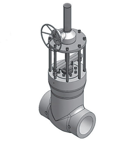
Slab gate valve and wedge gate valves are all designed for use in power, oil and gas industry applications. They are the main and commonly used types of gate valves. They have the similar structure form the appearance, when fully open, they do not have a bore through the gate itself and the gate retracts into the valve body, saves height space that is necessary for slab and expanding gate valves. Today here we will introduce the difference between slab and wedge type gate valve.


Slab Gate Valve

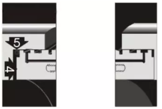
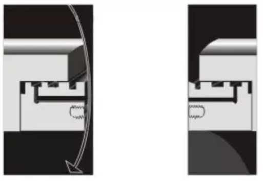
Slab gate valves are comprised of a single gate unit which raises and lowers between two seat rings. Due to the fact that the gate slides between the seats, slab gate valves are suitable for the medium with suspended particles. The sealing surface of slab gate valves is virtually self-positioned and is not damaged by the thermal deformation of the body. Even if the valve is closed in a cold state, the hot elongation of the stem does not overload the sealing surface, and slab gate valves without diversion holes do not require high precision in the closing position of the gate. When the valve is fully open, the bore through is smooth and linear, the flow resistance coefficient is minimal, piggable and no pressure loss.

Slab gate valves also have some disadvantages: when the medium pressure is low, the metal sealing surface may not seal completely, instead, when the medium pressure is too high, the highly-frequency opening and closing may make the sealing surface wear too much when there is no medium or lubrication. Another drawback is that a circular gate that moves horizontally on a circular channel controls flow effectively only when it is at 50% of the valve’s closed position.

Slab gate valves applications

Single or double-disc slab gate valves are suitable for oil and gas pipelines with DN50-DN300, class150-900 / PN1.0-16.0 Mpa, operating temperature -29 ~ 121℃. In the case of pipeline with piggable design, use a rising stem gate valve with a diversion hole. The slab gate valve with a diversion hole with a dark rod floating seat is suitable for oil and gas recovery wellhead device. The product oil pipeline and storage equipment shall use a single gate or double gate flat gate valves without diversion holes.

Wedge type gate valves

Wedge gate valves are comprised of a tapered gate that is metal-to-metal sealing. Compared with a slab gate valve, wedge gate valves are not piggable because of the void that is left in the bottom of the valve body when the valve is open. The wedge design increases the auxiliary sealing load, enabling metal sealed wedge valves to seal at both high and low medium pressures. However, wedge gate valves with metal seals are often unable to achieve the inlet seal due to the specific pressure of the inlet seal caused by the wedge action. Wedge gate valves have a certain Angle, generally, 3 degrees or 5 degrees, resulting in accumulated material in the lower groove of the valve, the medium with the particulate matter may damage the sealed seat, make loose closure.

Wedge gate valve application

Wedge gate valves are generally used where has no strict requirements of the size of the valve and harsh occasion. Such as high temperature and high pressure working medium, the requirements to ensure the closure of the long – term sealing conditions. Normally, for the environment with reliable sealed performance, high pressure, high-pressure cut-off (differential pressure) and low pressure by the (small) differential pressure, low noise, have spirit point and evaporation phenomena, the high temperature, low temperature, cryogenic medium, it is recommended to use wedge gate valve such as the electric power industry, oil refining, petrochemical, offshore oil, tap water and wastewater treatment engineering of urban construction, chemical industry, etc.


What’s Parallel Slide Gate Valves?

The Parallel Slide Gate Valves are mainly used in the field chemical, petroleum, natural gas designed to provide isolation and transmission of flow in a piping system or a component when closed, sometimes can be installed in the pump outlet for regulating or control of flow. It’s characterized by compact structure, reliable closing and good sealing performance, which can be furnished for high differential pressure services or where thermal. The parallel gate valve can be driven by the handwheel, electric motor, pneumatic and hydraulic.

Related Standards

Design and Manufacturing: API 6D;

Flange End Connection: ASME B16.5, ASME B16.47;

B.W. End Connection: ASME B16.25;

Inspection and Test: API 598.


How does parallel slide gate valve work?

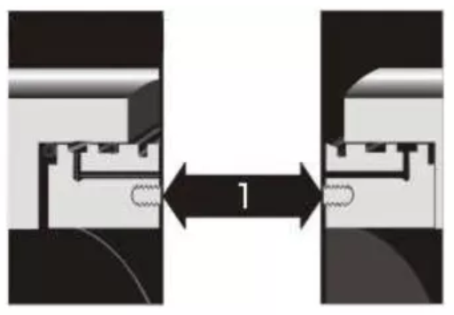
The parallel gate consists of the valve body, bonnet, disc assembly, stem and top works, each side of the valve can withstand full differential pressure. Replaceable double-disc seal with double bleeding and blocking (DBB) is created by a combination of internal pressure and spring force. The floating seat can automatically relieve pressure when the middle chamber is under pressure. When the pressure in the cavity is greater than that in the channel, the cavity pressure will be released to the channel. When the upstream pressure of the channel is greater than that of downstream (the valve is closed), the pressure in the middle chamber will be discharged to the upstream side channel. When the upstream pressure of the channel is equal to the downstream (the valve is fully open), the pressure in the middle chamber can realize the discharge of bilateral channels. The valve seat automatically resets after pressure relief.

  1. When the pressure inside the valve (cavity, inlet and outlet) is equal or no pressure, the disc is closed and the PTFE sealing ring on the seat surface forms the initial seal. The seat ring can automatically clean the sealing surface on both sides of the disc every time the valve is opened or closed.
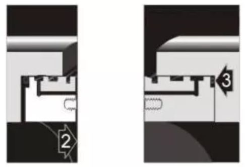
  2. Medium pressure acting on the inlet side disc, forcing the disc moves toward the exit seat PTFE ring, compress until it compaction in the metal valve seat sealing surface, formed the hard and soft double seal, namely PTFE to metal seal, metal to metal seal, export seat also is pushed to the body seat hole on the end face of the O-ring seat ring and valve sealing.
  3. The inlet seal forms after the pressure in the cavity relief, and the medium pressure forces the inlet seat to move to the disc. At this time, the inlet seat produces soft PTFE to metal seal and metal-to-metal seal, the O-ring guarantees the sealing of the seat outer ring with the valve body.
  4. Automatic pressure relief of the valve. When the pressure in the cavity of the valve body is greater than the pipe pressure, the inlet seat is pushed to the disc end of the upstream seat hole under the pressure difference, and the excess pressure between the upstream seat and the sealing surface of the disc of the valve body is discharged into the upstream pipe.


Parallel slide gate valve applications

  1. Oil and natural gas production wellhead device, conveying and storage pipelines (Class150~900/PN1.0~16.0MPa, operating temperature -29~121℃).
  2. Pipes with suspended particle media.
  3. Urban gas pipeline.
  4. Water engineering.

The surface treatment of ball part in ball valve

The ball valve has been widely used in industrial applications due to its small flow resistance, a wide range of pressure and temperature use range, good sealing performance, short opening and closing time, easy installation and other advantages. The ball is an important part that plays a key role in the opening and closing function for the ball valve. In order to enhance the sealing performance and hardness of the ball, it is necessary to pre-treat the surface of the ball. So what do you know about common surface treatments for the ball body?

  1. Nickel or chromium plating

Carbon steel body soft seated ball valve has poor corrosion resistance, the surface of the ball can avoid corrosion by electroplating a layer of alloy metal. Electroplating is the process of plating a thin layer of other metals or alloys on the metal surface by using the principle of electrolysis, so as to improve the corrosion resistance, abrasion resistance and surface aesthetics of the metal. When the ball is Austenitic stainless steel and the sealing ring is PEEK, it is suggested that the surface of the ball be plated with Nickel (ENP) or Chromium (HCr) to improve the hardness of the ball and seal. The coating thickness is generally 0.03mm ~ 0.05mm and above if there are special requirements that can be appropriately thickened, through this the plated ball hardness can be up to 600HV ~ 800HV.

2. Cold sprayed tungsten carbide

Cold spraying is a process in which compressed air accelerates metal particles to a critical velocity (supersonic) and physical deformation occurs after the metal particles impact directly on the surface of the substrate. The metal particles are firmly attached to the substrate surface, and the metal particles are not melted during the whole process. The advantage of cold spray is that the ball does not need to be heated, deformation and internal stress will not be generated in the spraying process, the thickness is well controlled, but the surface adhesion is not as good as that of spray welding.

Tungsten carbide is characterized by high hardness and good wear resistance, but the melting point is much higher than the general metal material point, about 2870℃, so only cold spraying tungsten carbide (WC) process can be used. The 0.15mm~0.18mm thickness of spraying tungsten carbide can achieve the ideal surface hardness, if there are special requirements can be up to 0.5mm ~ 0.7mm, the thicker the thickness of cold spray, the lower the surface adhesion, not recommended to use a thick cold spray thickness. The hardness of cold sprayed on the surface is generally 1050HV~1450HV (about 70HRC).

  1. Spray welding or cold spraying of Nickel-base alloy/Cobalt-based alloy

Ball valves usually use spray welding or cold spraying of nickel-based alloy inclnel600 on the ball. The process of spray welding is basically the same as that of thermal spraying, but the remelting process is added in the process of powder spraying. The commonly used cobalt-based alloy on the ball valve ball is STL20, STL6 and STL1, which is usually used for spray welding. The general thickness of spray welding cobalt-based alloy is 0.5mm ~ 0.7mm, and the actual maximum thickness can be up to 2.5mm~3mm. The hardness after spray welding is generally STL20:50~52HCR; STL6:38 ~ 40 HCR; STL1:48 ~ 50 HCR4,

  1. Nitriding treatment

Nitriding treatment refers to a chemical heat treatment process in which nitrogen atoms penetrate into the surface layer of the workpiece at a certain temperature and medium. Nitriding treatment can improve the wear resistance, fatigue resistance, corrosion resistance and high-temperature resistance of metal. The essence of nitriding treatment is to infiltrate nitrogen atoms into the surface layer of the ball. During the friction process between the seat and the ball, the nitride layer is easy to be worn or thinned for the hard seated ball valve, resulting in the ball is easy to be scratched by impurities in the medium, affecting the seal and even making the torque increase.

API 6D VS API 608 ball valve

API 6D “specification for piping and pipeline valves” and API 608 ” specification for flanged, threaded and welded metal ball valves” provide detailed requirements for ball valves in terms of structural design, performance requirements, test methods and other aspects. API 6D and API 608 constitute together a complete specification of ball valves in the petrochemical field, and each has its own characteristics according to different working conditions and requirements. API 608 adds the requirements like design, operation and performance based on ASME B16.34 “flanged, threaded and welded valves for general industrial use”. API 6D is more used for long-distance pipeline engineering and specified the differs from API 608 in terms of structure and function.

Applications and Structure
API 608 ball valve is used for the petrochemical industry pipeline media opening or cutting off, which is under the environment such as high temperature and high pressure, inflammable and explosive, corrosive and continuous operation, where require more requirements on valve sealing, material, corrosion. API 608 ball valve has a fixed ball structure and floating ball structure and mainly floating ball structure.
API 6D ball valves are specially used for long-distance pipeline transportation. In addition to switching on or cutting off the medium, the ball valve under this standard also has functions such as blowdown, emptying, overpressure relief, grease injection and on-line leak detection. API 6D ball valves are almost fixed ball construction. In consideration of environmental protection and economy, the blowdown/empty-out of the pipeline ball valve is more important.
API 6D ball valve can choose other structure design or materials to ensure the sealing performance of the valve, such as using the body structure with large storage space, increasing the diameter of the body cavity, etc., to avoid sand and stones and other foreign matters in the pipe to stay in the cavity for a long time and prevent damage to the seat and the ball.

Inspection and Testing
API 608 provides for the inspection, inspection and pressure testing of ball valves in accordance with API 598” inspection and testing of valves”. As a supplement to ASME B16.34, API 608 ball valves shall also fully meet ASME B16.34” inspection and test requirements”. ASME B16.34 and API 598 are basic specifications for general purpose valves.
API 6D provides more detailed requirements for the inspection and testing of pipeline valves, which are more demanding than ASME B16.34 and API 598, such as longer pressure duration, more test items, and more complex operating procedures.API 608 ball valves usually test the seal by pressurizing one end and observing the seat at the other end during the seal test, while API 6D ball valves test the seal from the middle chamber by pressurizing one end.
The latest API 6D 2014 version has added the requirements of QSL. QSL includes detailed requirements for nondestructive testing (NDE), pressure testing and manufacturing procedure documentation. Each QSL required API 6D ball valve inspection and test items are also different, QSL-1 is the minimum quality specification level specified by API 6D, the higher the QSL grade, the more stringent the requirements, the buyer can specify that the ball valve should conform to QSL- (2 ~ 4) quality specification level.

Installation and Maintenance
API 608 ball valves can be installed in the factory, easy to store and transport. API 6D ball valve is used for long-distance oil and gas pipeline, with a large diameter and harsh environment, and daily maintenance needs to be strengthened. The API 6D ball valve is difficult to replace and has high maintenance cost due to factors such as caliber, buried installation and welding connection with pipelines. Therefore, the API 6D ball valve of the long-distance pipeline requires higher safety reliability, tightness and strength than API 608 ball valve to ensure long-term safe and reliable operation of the long-distance pipeline.
In general, the API 6D ball valve is primarily used in oil and gas industry pipeline systems, including long-distance oil and gas pipelines including ASME B31.4 and B31.8, with a diameter range of NPS (4 ~ 60) and pressure levels of 150, 300, 400, 600, 900, 1500,2500. Generally fixed ball structure, sealed at the inlet. API 608 ball valves are used in petroleum, petrochemical and industrial applications, mainly for ASME B31.3 process pipeline, diameter range NPS (1/4 ~ 24), small diameter, pressure class 150, 300, 600, 800 pounds, generally floating ball structure, sealed at the outlet.

The materials for valve packing

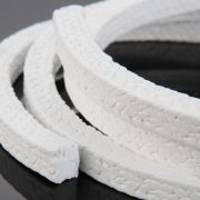
Valve packing is a kind of dynamic sealing structure which is installed between the valve stem and the packing box of the valve cover to prevent outside leakage. Packing material, reasonable packing box structure and installation methods ensure the valve reliable sealing performance. There are various valve sealing packing materials are available and different packing suitable for different working conditions, including asbestos, graphite, PTFE, etc.

  • Flexible graphite packing

Flexible graphite packing is the most widely used material in the valve, which can be pressed molding, has been widely used in the field of petroleum, chemical industry, power generation, chemical fertilizer, medicine, paper, machinery, metallurgy, aerospace and atomic energy and other industries wherewith the nominal pressure ≤32MPa. It has the following excellent performance:

Good flexibility and resilience. The incision packing can be freely bent more than 90° in the axial direction and will leak-free due to the change of temperature/pressure/vibration, safe and reliable; Good temperature resistance. The wide range of -200℃-500℃ usages, even in non-oxidizing medium up to 2000℃ and maintain excellent sealing; Strong corrosion resistance. It has good corrosion resistance to acid, alkali, organic solvent, organic gas and steam. Low friction coefficient, good self – lubrication; Excellent impermeability to gases and liquids; Long service life, can be repeated use.

  • PTFE packing

Polytetrafluoroethylene packing has good lubrication, weaving polytetrafluoroethylene packing has excellent corrosion resistance, and can be used for cryogenic medium, but its temperature resistance is poor generally only used in the temperature below 200℃ conditions, while can not be used for melting alkali metal and high temperature of fluorine, hydrogen fluoride medium.

  • Vegetable fiber packing

Made of hemp or cotton impregnated oil, wax or other anti-seepage materials, used for low-pressure valves below 100℃ and media like water, ammonia and etc.

  • Asbestos packing

Asbestos fiber has better heat resistance, absorption and strength can withstand weak acid, strong alkali. Inked asbestos, rubber asbestos and oil-impregnated asbestos are suitable for valves with the steam temperature of 450℃.

  • Rubber filler

Rubber cloth, rubber rod, ring rubber packing for temperature ≤140℃ ammonia, concentrated sulfuric acid and other media.

  • Carbon fiber packing

The carbon fiber filler is made of polytetrafluoroethylene emulsion impregnated with carbon fiber is a woven rope. Carbon fiber packing has excellent elasticity, excellent self-moistening and high-temperature resistance. It can work stably in the air temperature range of -120 ~ 350℃, and the pressure resistance is less than 35MPa.

  • Metal + rubber packing

It can include metal-wrapped packing, metal laminated packing, metal corrugated packing, lead packing, etc. The metal wrapped packing and metal laminated packing is characterized by high-temperature resistance, erosion resistance, abrasion resistance, high strength, good thermal conductivity, but poor sealing performance must be used with plastic packing, its temperature, pressure, corrosion resistance that depends on metal material.

  • Stainless steel wire + flexible graphite woven packing

Generally, v-shaped packing is composed of upper packing, middle packing and lower packing. The upper and middle packing is made of PTFE or nylon, and the lower packing is made of 1Cr13, 1Cr18Ni9 and A3 steel. PTFE can withstand high temperature 232℃, nylon 93℃, general pressure 32MPa, often used in corrosive media.

Generally speaking, the valve packing materials are mainly PTFE and flexible graphite, be noted that the packing box dimension accuracy, roughness, stem surface dimension accuracy also affect packing seal performance.

What is a valve body?

The valve is a type of device used to control, change or stop the moving components of flow direction, pressure and discharge in the pipeline system. The valve body is a main part of valve. It is made by different manufacturing processes according to pressure class, such as casting, forging, etc. Valve body with low-pressure is usually cast while valve body with medium and high pressure is manufactured by the forging process.

The Materials for Valve Body
The commonly used materials of valve body are: cast iron, forged steel, carbon steel, stainless steel, Nickel-based alloy, copper, titanium, plastic, etc

Carbon steel
In the oil and gas industry, the most commonly used material for valve body is ASTM A216(for casting) and ASTM A105(forging). For low-temperature service, ASTM A352 LCB/LCB for cast and ASTM A350 LF2/LF3 for forged bodies are used.

Stainless steel
When there are more requirements for the temperature, pressure or corrosion increase, stainless steel bodies become necessary: ASTM A351 CF8 (SS304) and CF8M (SS316) for cast devices, and the various ASTM A182 F304, F316, F321, F347 for forged types. For specific applications, special material grades are used such as duplex and super steels (F51, F53, F55) and nickel alloys (Monel, Inconel, Incoloy, Hastelloy) for valve bodies.

Non-ferrous
For more severer applications, non-ferrous materials or alloys like, Aluminum, Copper, Titanium alloys and other plastic, ceramic material combining alloys can be used for body manufacturing.

The End Connections of Valve Body
Valve body can be connected to other mechanical devices and pipes in different ways. The main end types are flanged and buttweld (for devices above 2 inches) and socket weld or threaded/screwed (NPT or BSP) for small diameter devices.

Flanged End Valve
Flanged ends are the most frequently used form of connection between valves and piping or equipment. It is a detachable connection with flange, gasket, stud bolts and nuts as a group of sealing structure.

Indicated by the ASME B16.5 specification, flange connection can be applied to a variety of larger diameter valves, and nominal pressure valves, but there are certain restrictions on the use temperature, in high-temperature conditions, due to the flange connection bolts easy to creep phenomenon and cause leakage, generally speaking, flange connection is recommended to use at a temperature ≤350℃.

The flange face may be raised (RF), flat (FF), ring joint, tongue and groove and male & female and be finished in any of the available variants (stock, serrated or smooth).

Welding Ends Valve
Welding connection between valve and pipeline can be butt welding connection (BW) and socket welding connection (SW) used for high-pressure pipelines (socket weld for smaller sizes, below 2 inches, and buttweld for larger diameters). These welded connections are more expensive to execute than flanged joints, as they require more work, but are more reliable and less prone to leakages in the long run.

Valves with socket weld ASME B16.11 or buttweld ends ASME B16.25 are welded with the connecting pipe. Buttweld connections require full welding of the beveled ends of the two parts to be joined, whereas socket weld connections are made by fillet welds.

Threaded End Valve
This is a simple connection and often used for low-pressure or small valves below 2 inches. The valve is connected to the pipe by a tapered thread ends, which may be BSP or NPT. Threaded connections are cheaper and easier installation, as the pipe is simply screwed onto the valve, stud bolts or welding operations without the need for flanges.