The selection of valve operation modes

Depending on the mode of operation, the valve can be divided into the manual valve and an actuator driven valve. Valve actuators are devices that operate and are connected to the valve, controlled by hand (handwheel/spring lever), electric (solenoid /motor), pneumatic (diaphragm, cylinder, blade, air engine, film and ratchet combination), hydraulic (hydraulic cylinder/hydraulic motor) and combination (electro &hydraulic, pneumatic &hydraulic).

Valve drive device can be divided into straight stroke and angle stroke according to the motion modes. The straight stroke drive device is multi-turn drive, mainly suitable for various types of gate valves, globe valves and throttle valves; The angular stroke drive device is a partial rotary drive device that only needs a 90° angle. mainly applicable to various types of ball valves and butterfly valves. The selection of valve actuators should be based on a full understanding of the type and performance of the valve actuators, depending on the type of valve, the operating specification of the device and the position of the valve on the line or device.


Valve with self-acting by fluid

The automatic valve is to rely on the energy of the medium itself to open and close the valve does not need external force drive such as safety valve, pressure reducing valve, steam trap, check valve, automatic regulating valve.


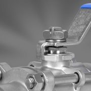
Handwheel or lever valve

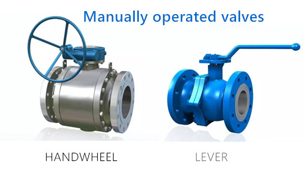
Manual operated valves are the most widely used type of valve, that are manually driven valves with handwheels, handles, levers, and chain wheels.  When the opening and closing torque of the valve is larger, this wheel or worm gear reducer can be set between the handwheel and the valve stem. Universal joint and driveshaft can also be used when remote operation is necessary.

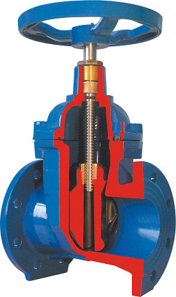
Manually operated valves are usually equipped with a handwheel attached to the valve’s stem or Yoke nut which is rotated clockwise or counterclockwise to close or open a valve. Globe and gate valves are opened and closed in this way.

Hand-operated, quarter-turn valves, such as Ball valve, Plug valve or Butterfly valve, which need a lever to actuate the valve. While there are applications where it is not possible or desirable to actuate the valve manually by handwheel or lever. In these situations may be the actuators are needed.


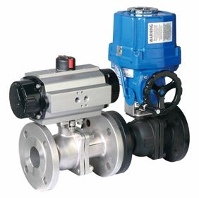
Valve drove by actuators

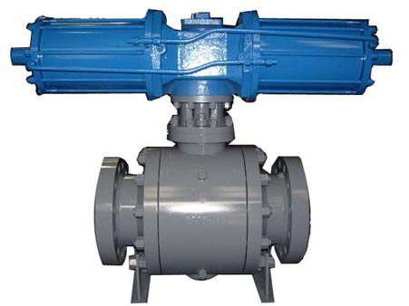
An actuator is a driving device that provides linear or rotational motion, utilizing a certain source of power and operating under a certain control signal. Basic actuators are used to fully open or close a valve. Actuators for controlling or regulating valves are given a positioning signal to move to any intermediate position. There many different types of actuators, the commonly used valve actuators are showed below:

  • Gear Actuators
  • Electric Motor Actuators
  • Pneumatic Actuators
  • Hydraulic Actuators
  • Solenoid Actuators

Large valves must be operated against high hydrostatic pressure and they must be operated from a remote location. When the time for the opening, closing, throttle or manually controlling the valve is longer, than required by system-design standards. These valves are usually equipped with an actuator.


Generally speaking, selecting the actuators that depend on several factors like the valve type, operation intervals, torque, switch control, continuous control, external power availability, economy, maintenance and so on being these factors dependable on each situation.

The leak rates standards of industrial valve

Valves are one of the main leakage sources in the pipeline system of the petrochemical industry, so it’s critical to the leakage of valves. Valve leakage rates are actually the valve sealing level, valve sealing performance is referred to as the valve sealing parts to prevent the ability of media leakage.

The main sealing parts of the valve including: the contact surface between the opening and closing parts and the seat, the fitting of packing and stem and packing box, the connection between the valve body and the bonnets. The former belongs to internal leakage, which directly affects the ability of the valve to cut off the medium and the normal operation of the equipment. The last two are external leakage, that is, media leakage from the inner valve. The loss and environmental pollution caused by external leakage are often more serious than that caused by internal leakage. Valve leakage is not allowed especially for high temperature and pressure condition, flammable, explosive, toxic or corrosive media, so the valve must provide reliable sealing performance to meet the requirements of its use conditions on the leakage. At present, there are five kinds of valve seal classification standards commonly used in the world.


ISO 5208

International Organization for Standardization ISO 5208 specifies examinations and tests that a valve manufacturer needs to act upon in order to establish the integrity of the pressure boundary of an industrial metallic valve and to verify the degree of valve closure tightness and the structural adequacy of its closure mechanism.

There are 10 leakage rates specified in ISO 5208: A, AA, A, B, C, CC, D, E, EE, F, G and the rate A is the highest grades. There is a loosely defined correspondence between the leakage rate acceptance values of API 598 and leakage value rate A as applied to DN 50, rate CC-liquid for other than metal-seated check valves and for check valves rate EE-gas and rate G-liquid. Rate A, B, C, D, F and G correspond to values in EN 12266-1.

API 598

American petroleum institute standard API 598 is the most commonly used test standard for American standard valves. It is applicable to the following API standard valve sealing performance tests:

API 594 Flanged, lug, wafer and butt weld connection check valves

API 599 Flanged, threaded and butt-welded metal plug valves

API 602 Steel gate and check valves DN 00 and below for the oil and natural gas industry

API 603 Flanged and butt-welded corrosion-resistant bolted cover gate valves

API 608 Flanged, threaded and butt-welded metal ball valves

API 609 Double flanged, lug and wafer butterfly valves

MSS SP61

American Association for standardization of manufacturers of valves and fittings MSS SP61 pressure test for metallic valves specifies the allowable leakage requirements are as follows:

(1) In the case that one of the sealing surfaces of the valve sealing seat is made of plastic or rubber, no leakage shall be observed during the duration of the sealing test.

(2) The maximum allowable leakage on each side when closed shall be: the liquid shall be the nominal size (DN) 0 per mm, 0 per hour.4 ml; Gas is the nominal size (DN) per millimeter, 120 ml per hour.

(3) The leakage allowed by the check valve can be increased by 4 times.

It should be noted that MS SSP 61 is often used for inspection of “fully open” and “fully closed” steel valves, but not for control valves. MSS SP61 is not usually used for testing American standard valves.

ANSIFCI 70-2

American national standards/American instrument association standards ANSI/FCI 70-2(ASME B16).104) is applicable to the control valve seal grade requirements. Metal-elastic seal or metal seal should be selected in engineering design according to the characteristics of the medium and the opening frequency of the valve. Metal seated valve seal grades should be is stipulated in the order contract, the rates I, Ⅱ, Ⅲ is used less due to request a lower level, generally choose Ⅳat least and V or Ⅵ for higher requirements.

EN 12266—1

EN 12266-1, tests on industrial valves part l specifies the pressure tests, test methods and acceptance criteria – mandatory requirements. EN 12266-1 meets the requirements of ISO 5208 for seal classification but lacks AA, CC and EE ratings. The new edition of ISO 5208 adds six levels of AA, CC, E, EE, F, and G and gives comparisons with several seal levels of API 598 and EN 12266.


It should be noted in the engineering design that API 600-2001(ISO 10434–1998) specifies that the sealing performance of the valve is tested in accordance with ISO 5208, but the leakage in tables 17 and 18 is equivalent to API 598–1996, not ISO 5208. Therefore, when API 600 and its sealing performance test API 598 standard are selected for the engineering design, the version of the standard must be clarified to ensure the uniformity of the standard content.

The relevant guidelines of API 6D(ISO 14313) for valve leakage are: “soft seated valves and oil-seal plug valves shall not exceed ISO 5208 A (no visible leakage), metal seat valves shall not exceed ISO 5208(1993) D unless otherwise specified.” Note in the standard: “special applications may require leakage less than ISO 5208(1993) class D. Therefore, leakage requirements higher than the standard shall be given in the order contract.


Full port ball valve VS reduced port ball valve

As we all know that the ball valve can be divided into full port ball valve and reduced ball valves according to the flow passage form. A full port ball valve, commonly known as full bore ball valve has an over-sized ball so that the hole in the ball is the same size as the pipeline resulting without obvious limitations, is mainly used in switches and circuit applications. Reduced ball valves, also known as the standard port valve, are valves with the opening of the closing part to control flow, of which area is less than of the inner diameter of the pipeline.

There is no valve standards concept for full port ball valves and reduced ball valves. ASTM, GB only requires the ball valve to be tested for pressure drop while the Korean standard made provisions on their concept: valve ball diameter less than or equal to 85% of the ball valve port diameter is called reduced ball valve, ball valve diameter greater than 95% of the ball valve port diameter is called full diameter ball valve. Generally speaking, a full port ball valve is equal width channel, its size can not be less than the nominal size specified in the standard, such as DN50 full diameter ball valve channel diameter is about 50mm. The inlet of reduced diameter ball valve passage is larger than the diameter of the passage, and the actual diameter of the passage is probably smaller than this specification. For example, the diameter of the DN50 reduced diameter ball valve is about 38, roughly equivalent to DN40.

Medium:

The full port ball valve is mainly used for conveying viscous, easy slagging medium, regular cleaning convenient. The reduced port ball valve is mainly used for conveying gas or medium physical performance similar to water in the pipeline system, its weight about 30% lighter than the full port ball valve, and the flow resistance is only 1/7 of the same diameter of the globe valve.

Application:

The full port ball valve offers small flow resistance, especially suitable for demanding conditions. Fully welded full port ball valves are required for buried landowners in oil and gas pipelines. The reduced port ball valve is suitable for some low requirements, low convection resistance requirements and other conditions.

Pipeline circulation capacity:

Experimental tests have shown that when the valve inner diameter is greater than 80% of the pipe end inner diameter, it has little effect on the pipeline fluid flow capacity. On the one hand, the reduced diameter design reduces the flow capacity of the valve (Kv value), increases the pressure drop at both ends of the valve, and causes the loss of energy, which may not have a great impact on the pipeline but increases the erosion of the pipeline.


In general, reduced port ball valve has a smaller size, smaller installation space, about 30% than the full port of the ball valve weight, is conducive to reduce the pipe load and transportation costs, extends the service life of the valve, also cheaper. For full port ball valve, flow is unrestricted but the valve is larger and more expensive so this is only used where free flow is required, for example in pipelines which require pigging.

Valve pressure test of DBB and DIB ball valve

DBB (double block and bleed valve) and DIB (double isolation and bleed valve) are two kinds of commonly used seat sealing structures for trunnion mounted ball valves. According to API 6D, DBB ball valve is a single valve with two sealed auxiliary, the closed position of which provides the pressure seal at both ends of the valve by means of bleed of the body cavity between the two seal surfaces, if the first seal leaks, the second will not seal in the same direction. DIB ball valve is a single valve with two seating surfaces, each of these seal seat provides a single source of pressure seal in the closed position by discharging the valve chamber between the seal seats.


The pressure test of the DBB valve:

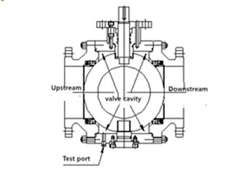
The valve is partially opened so that the experimental flow is fully injected into the valve chamber, and then the valve is closed so that the bleeding of the valve body is open and the excess medium is allowed to overflow from the valve chamber test junction. Pressure should be applied simultaneously from both ends of the valve to monitor seat tightness through overflow at the valve chamber test junction. The figure below shows a typical DBB ball valve configuration.

When the valve is closed and the valve chamber test port is opened and both ends of the valve are pressurized (or pressurized separately), the valve chamber port detects leakage from each end to the valve chamber. Theoretically, DBB valve can not provide positive double isolation when only one side is under pressure, the valve does not provide positive double isolation when only one side is under pressure.


The pressure test of DIB-1(Two bi-directional sealing seats)

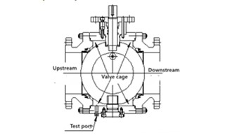
Each seat shall be tested in both directions and the installed cavity pressure relief valve shall be removed. The valve shall be half-opened so that the valve and valve chamber shall be injected with the test medium until the test liquid spills through the test port of the valve chamber. Close the valve to prevent leakage of the chamber in the direction of the test seat, the test pressure shall be applied successively to each end of the valve to test the leakage of each seat upstream separately, and then to test each seat as the downstream seat. Open both ends of the valve to fill the cavity with media and then pressurize while observing leakage of each seat at both ends of the valve.

Because the pressure in the cavity of the DIB-1 valve cannot be released automatically, when the temperature of the valve is abnormally raised, the volume of the medium in the valve cavity increases accordingly, thus forcing the pressure in the cavity to increase automatically. When the pressure reaches a certain level, it will be very dangerous, so the cavity of the DIB-1 valve must be installed with a safety valve.


The pressure test of DIB-2(One bi-directional and one unidirectional sealing seat)

One of the seats of the DIB-2 valve can withstand pressure from either the chamber or the end of the valve in any direction without leakage. The other seat can only withstand pressure from the end of the valve. When the valve is closed and the valve chamber test interface is open and both ends of the valve are pressurized (or pressurized separately), the valve chamber test interface can detect whether there is leakage from each end to the valve chamber. Two-way seat test should be pressurized valve chamber and valve upstream observe whether the downstream valve leakage.

The advantage of the valve is tight protection for the valve, the valve closed after the medium will never enter the pipeline downstream, at the same time when the cavity pressure abnormal rise can automatically pressure relief to the upstream of the valve. Please note that the valve installation direction requirements, the opposite direction is the same as DBB.


Both DBB and DIB valves have their unique application and media, and various environmental challenges where critical isolation is needed to ensure that leakage does not occur such as LNG, petrochemical, transmission and storage, natural gas industrial processes, mainline and manifold valves in liquid pipelines, and refined products transmission lines.

PTFE lined valve VS PFA lined valves

Lined valves are a safe and reliable solution to any level of corrosion flow for chemical industrial. The lining of the valves and fittings ensures extremely high chemical resistance and longevity. PTFE lined valve and PFA lined valves are the commonly used valves that used as more economic alternatives to high-grade alloys in corrosive applications in the chemical, pharmaceutical, petrochemical, fertilizer, pulp and paper, and metallurgical industries. To know their difference, you must to know the material differences between PTFE and PFA.

Both of PFA and PTFE are the commonly used forms of Teflon. PFA and PTFE have similar chemical properties: excellent mechanical strength and stress-cracking resistance. The features of good molding performance and wide processing range made it’s suitable for molding, extrusion, injection, transfer molding and other molding processing, can be used for making wire and cable insulation sheath, high-frequency insulation parts, chemical pipelines, valves and pumps corrosion-resistant lining; Machinery industry with special spare parts, textile industry with a variety of anticorrosive materials electrode, and so on.

PTFE (Teflon) is a polymer compound formed by the polymerization of tetrafluoroethylene with excellent chemical stability, corrosion resistance, sealing, high lubrication and non-viscosity, electrical insulation and good aging resistance for media such as strong acid, strong alkali, strong oxidant. Its operating temperature is -200 ~ 180℃, poor fluidity, large thermal expansion. PTFE Lined valves ensures extremely high chemical resistance and longevity, can be widely used in corrosive applications in the chemical, electric machinery, pharmaceutical, petrochemical, fertilizer, pulp and paper, and metallurgical industries.

PFA (Polyfluoroalkoxy) is a high-performance thermoplastic material with improved viscosity developed from PTFE. PFA has similarly excellent performance as PTFE but superior to PTFE in terms of flexibility, which is the more popularly known form of Teflon. What distinguishes it from the PTFE resins is that PFA is melt processable. PFA has a melting point of about 580F and a density of 2.13-2.16 (g/cm3). Its service temperature is -250 ~ 260 ℃, it can be used for up to 10000h even at 210 ℃. It features excellent chemical resistance, resistance to any strong acid (including water), strong alkali, grease, insoluble in any solvent, excellent aging resistance, almost all viscous substances can not adhere to its surface, completely no combustion. Tensile strength (MPa) > 23, elongation (%) > 250.

In general, the combined performance of PFA lined valves is much better than PTFE lined valves. PTFE valve is more common and popular due to its cheaper cost, PFA is more often used in industrial applications, particularly industrial tubing and valves. PFA lined valve guarantees high sealing performance in the large range of pressure and temperature difference and is suitable for transportation of liquid and gas media in various industrial pipelines, such as sulfuric acid, hydrofluoric acid, hydrochloric acid, nitric acid and other highly corrosive media.

We offer the lined ball valve, plug valves and gate valves that are leak-free and have minimal operating and maintenance costs. In addition to the standard PTFE lining, we can also offer anti-static lining from PFA. If you’d like to find out more information, call us today!.


Rising stem gate valve VS non-rising stem gate valve

Gate valve is a kind of valve for medium connection and shut- off but not suitable for regulating. Compared with other valves, gate valves have a wider range of combined applications for pressure, service fluid, design pressure and temperature. According to the screw position of the stem, the gate valve can be divided into rising stem gate valves and Non-rising stem gate valve (NRS).

Stem nut for open stem gate valve is on its cover. Rotation of stem nut drives stems up and down when opening or closing gate valve. It opens and closes the disc connected to the stem by lifting or lowering the thread between the handwheel and the stem and fully open position does not disrupt the flow. This design is favorable to the lubrication of the valve stem and has been widely used. The wedge is rubber coated and It is not used as a check valve and flow rate adjustments.


The advantages disadvantages of rising stem gate valve:

  • Easy to open and close.
  • Small fluid resistance, sealing surface by medium erosion and erosion.
  • Medium flow is not restricted, no turbulence, no pressure reduction.
  • The sealing surface is easy to be eroded and scraped, difficult for maintenance.
  • Larger structure requires more space and long-time opening.


Non-Rising Stem means outside stem, also referred to as the rotary stem gate valve or blind stem wedge gate valve. In an NRS valve, the stem will turn to open and close the gate, but the stem does not move up or down as it turns. As the stem turns, it moves into or out of the valve, which also moves the gate to open or seal the valve.

The advantages and disadvantages of non-rising stem gate valve:

  • Non-rising stem valves take up less space, ideal for gate valve with limited space. Generally, an open-close indicator should be installed to indicate the degree of open-close.
  • Failure to lubricate stem threads will result in medium erosion and easy damage.


What’s the difference between rising stem gate valve and non-rising stem gate valve?

  1. Appearance: The rising stem gate valve can be seen from the appearance whether the valve is closed or open. The lead screw can be seen while the non-rising stem gate valve cannot.
  2. The ascension screw of rising stem flanged gate valve is exposed outside, the nut cling to the handwheel is fixed (not rotating axial movement), the rotation of the screw and gate only relative motion without relative axial displacement of the disc and stem up and down together. The lifting screw of the non-rising stem flange gate valve only rotates and does not move up and down.