Bolt strength grades marking for valve

A bolt is a cylindrical body with external threads consisting of a head and a screw. As one of the most commonly used fasteners, it is used in conjunction with a nut to connect two parts with holes like valves. The bolts used for valve flange connection can be classified into 3.6, 4.6, 4.8, 5.6, 6.8, 8.8, 9.8, 10.9, 12.9 and etc. The bolts of class 8.8 and above are called high-strength bolts which made of low or medium carbon alloy steel after heat-treated (quenched and tempered). Bolt grades are composed of two numbers and a decimal point, which respectively represent the nominal tensile strength value and bending strength ratio of bolt material, where the first number multiplied by 100 represents the nominal tensile strength of the bolt; These two numbers are multiplied by 10 to give the bolt its nominal yield point or yield strength.


A strength rating of 4.6 bolt means:

  1. Nominal tensile strength reaches 400MPa;
  2. The bending strength ratio is 0.6;
  3. Nominal yield strength reaches 400×0.6=240 MPa

Strength grade 10.9 high strength bolt, indicating that the material can achieve the following after heat treatment:

  1. Nominal tensile strength up to 1000 MPa;
  2. The bending ratio is 0.9;
  3. Nominal yield strength reaches 1000×0.9=900 MPa

Bolt strength grade is an international standard. Strength grades 8.8 and 10.9 refer to shear stress grades 8.8 and 10.9 GPa for bolts.8.8 nominal tensile strength 800 N/MM2 nominal yield strength 640N/MM2. The letter “X.Y” indicates the strength of the bolt, X*100= the tensile strength of the bolt, X*100*(Y/10)= the yield strength of the bolt (as specified: yield strength/tensile strength =Y/10). For example, the tensile strength of class 4.8 bolts is 400MPa; Yield strength: 400*8/10=320MPa. But there are exceptions, such as stainless steel bolts are usually labeled A4-70, A2-70.


Bolt grade marking and corresponding material selection:

Strength class

Recommend material

Minimum tempering temperature

3.6 Low carbon alloy steel 0.15%≤C≤0.35%  
4.6 Medium carbon steel 0.25%≤C≤0.55%  
4.8  
5.6  
5.8  
6.8  
8.8 Low Carbon Alloy Steel with 0.15%<C<0.35% 425
Medium carbon steel 0.25%<C<0.55% 450
9.8 Low Carbon Alloy Steel 0.15%< C < 0.35%  
Medium Carbon Steel 0.25%<C<0.55%
10.9 Low Carbon Alloy Steel with 0.15%<C<0.35% 340
Medium carbon steel 0.25%<C<0.55% 425

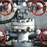
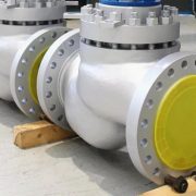
We are a fully stocked manufacturer and distributor of the flanged connected ball valve, bolted bonnet globe valve and we make the valve easy to find for your need. When installing and removing the valves, bolts should be tightened symmetrically, step by step and evenly. These valves bolt selection should refer to the following chart:

Valve DN Screw hole diameter(mm) Nominal bolt diameter(mm) Bolt number Valve thickness   (mm) Flange thickness        (mm) Nut

(mm)

Spring gasket (mm) Single screw length (mm) Bolt size
DN50 18~19 M16 4 0 20 15.9 4.1 68 M16*70
DN65 18~19 M16 4 0 20 15.9 4.1 68 M16*70
DN80 18~19 M16 8 0 20 15.9 4.1 68 M16*70
DN100 18~19 M16 8 0 22 15.9 4.1 72 M16*70
DN125 18~19 M16 8 0 22 15.9 4.1 72 M16*70
DN150 22~23 M20 8 0 24 19 5 80 M20*80
DN200 22~23 M20 12 0 26 19 5 84 M20*90
DN250 26~27 M22 12 0 29 20.2 5.5 91.7 M22*90
DN300 26~27 M22 12 0 32 20.2 5.5 97.7 M22*100
DN350 26~27 M22 16 0 35 20.2 5.5 103.7 M22*100


The material for high temperature industrial valve

Working temperature is a key factor should be taken into consideration for valve design, manufacture and inspection. Generally, the operating temperature t > 425℃ valve is referred to as a high-temperature valve, but the number is difficult to distinguish the temperature range of high temp valve. High temp valve including high temp gate valve, high temperature globe valve, high temperature check valve, high temperature ball valve, high temperature butterfly valve, high temperature needle valve, high temperature throttle valve, high temperature pressure reducing valve. Among them, the most commonly used are gate valve, globe valve, check valve, ball valve and butterfly valve. High temp valves are widely used in petrochemical, chemical fertilizer, electric power and metallurgy industries. According to ASME B16.34, the material of the valve body and interior part are different in each temperature range. In order to ensure the valve in accordance with its corresponding high temp working conditions, it is absolutely necessary to scientifically and reasonably design and distinguish the high temp level of valve.

Some high temp valve manufacturers divide high temperature valves into five grades according to temp rating based on its production experience. That is, the valve operating temperature t>425~550℃ is grade PI, t>550~650℃ is grade PII, t>650~730℃ is grade PIII, t>730~816℃ is grade PIV, and t>816℃ is grade PV. Among them, PI~PIV valve mainly depends on the selection of appropriate materials to ensure its performance, PV valve in addition to material selection is more important to use special design such as lining insulation lining or cooling measures. High-temperature valve design should pay attention to the use of temperature shall not exceed the maximum allowable use temperature of the material. According to ASMEB31.3, the maximum temperature of common high-temperature valve materials is shown in the following table. Special note is that in the actual design of the valve also consider the corrosive medium and stress levels and other factors, the allowable temperature of the valve material is actually lower than the table.


Pressure-temperature rating for commonly used stainless steel:

Workworn temp  Material Pound class working pressure, pounds per square inch
150 300 400 600 900 1500 2500 4500
800℉

(427℃)

CF8, 304, 304H 80 405 540 805 1210 2015 3360 6050
CF8M, 316, 316H 80 420 565 845 1265 2110 3520 6335
321, 321H 80 450 600 900 1355 2255 3760 6770
CK-20, 310, 310H 80 435 580 875 1310 2185 3640 6550
1000℉

(538℃)

CF8, 304, 304H 20 320 430 640 965 1605 2625 4815
CF8M, 316, 316H 20 350 465 700 1050 1750 2915 5245
321, 321H 20 355 475 715 1070 1785 2970 5350
CK-20, 310, 310H 20 345 460 685 1030 1720 2865 5155
1200℉

(650℃)

CF8, 304, 304H 20(1) 155 205 310 465 770 1285 2315
CF8M,316,316H 20(1) 185 245 370 555 925 1545 2775
321, 321H 20(1) 185 245 365 555 925 1545 2775
CK-20, 310, 310H 20(1) 135 185 275 410 685 1145 2055
1350℉

(732℃)

CF8, 304, 304H 20(1) 60 80 125 185 310 515 925
CF8M, 316, 316H 20(1) 95 130 190 290 480 800 1440
321, 321H 20(1) 85 115 170 255 430 715 1285
CK-20, 310, 310H 20(1) 60 80 115 175 290 485 875
1500℉

(816℃)

CF8, 304, 304H 10(1) 25 35 55 80 135 230 410
CF8M, 316, 316H 20(1) 40 55 85 125 205 345 620
321, 321H 20(1) 40 50 75 115 190 315 565
CK-20, 310, 310H 10(1) 25 35 50 75 130 215 385


Pressure – temperature rating of Cr – Mo high-temperature steel

Working temp Grades Pound class working pressure, pounds per square inch
150 300 400 600 900 1500 2500 4500
800℉

(427℃)

WC4, WC5, F2 80 510 675 1015 1525 2540 4230 7610
WC6, F11C1.2, F12C1.2, 80 510 675 1015 1525 2540 4230 7610
WC9, F22C1.3 80 510 675 1015 1525 2540 4230 7610
C5, F5 80 510 675 1015 1525 2540 4230 7610
1000℉

(538℃)

WC4, WC5, F2 20 200 270 405 605 1010 1685 3035
WC6, F11C1.2, F12C1.2, 20 215 290 430 650 1080 1800 3240
WC9, F22C1.3 20 260 345 520 780 1305 2170 3910
C5, F5 20 200 265 400 595 995 1655 2985


In short, high temp valve with the operating temperature higher than 425℃, the main material of which is alloy steel or stainless steel or Cr-Ni heat resistant alloy. Actually, in practice application, the material WCB(or A105) is also widely used in the main body of the valve, such as high-temperature ball valve, check valve and butterfly valve. When the working temperature of the ball valve with PTFE and rubber as sealing ring is higher than 150 ~ 180℃, it is not recommended to use the counterpoint polystyrene seat (working temperature t≤320℃) or metal seat, that is proper “high-temperature ball valve”.

What’s the Water hammer effect of valve?

When a valve is closed suddenly, the inertia of the pressurized flow creates a water shock wave that can cause damage to the valve or piping system. This is known as the “water hammer effect” in hydraulics or positive water hammer. On the contrary, the sudden opening of the closed valve can also produce water hammer effect, known as negative water hammer, which has a certain destructive force but is not as large as the positive water hammer.

The closing part is suddenly sucked into the seat when the valve is to close, it is called the cylinder blocking effect. This is caused by a low-thrust actuator that does not have enough thrust to remain close to the seat, causing the valve to suddenly close, creating a water hammer effect. In some cases, quick-opening flow characteristics of the control valve can also lead to the water hammer effect.

The water hammer effect is extremely destructive: too high pressure will cause the pipe and valves to breakage, and too low pressure will cause collapse, damaging valves and fixtures. It also makes a lot of noise, but the real damage to valves and piping are caused by mechanical failure. Because kinetic energy changes rapidly into static pipe pressure, water hammers can break through the pipe or damage pipe supports and joints. For valves, water hammer can produce severe vibration through the spool, which may lead to failure of the core, gasket or packing.

When the power is cut off and the machine stops, the potential energy of the pump water system will overcome the inertia of the motor and make the system stop sharply, which will also cause pressure impact and water hammer effects. To eliminate the serious consequences of the water hammer effect, any sudden pressure changes in the system must be prevented. In the pipeline need to prepare a series of buffer measures and equipment such as water hammer eliminator, water hammer pump station, straight water hammer pump.

To prevent pressure fluctuations, the valve should be closed at an even rate. For control valves that must be throttled when close to the seat, an actuator with a sufficiently large output thrust, such as a piston pneumatic or hydraulic actuator, or a special notch in the travel sleeve of a manually rotating operator, should be used to reduce or prevent cylinder blocking effects. Installing certain types of anti-surge equipment in the pipeline system can also reduce water hammer effects such as pressure relief valves or buffer drums. In addition, gas injection into the system reduces fluid density and provides some compressibility to handle any sudden fluctuations.


The valves used for steam pipeline system

Industrial processes frequently use steam at lower pressures and temperature. The steam is used for cleaning, heating, and humidification in the application of powering turbines to generate electricity. The steam pipeline of power plant requires some control and steam control to reduce the pressure and temperature of the inlet stream for process application.

In general, a complete steam station system must be equipped with the valve below: main control valve, control valve of each branch, steam pressure reducing valve, steam trap (drain water valve) according to the length of the pipeline, the bleeding valve in the pipeline end. Though most types of valves can control steam flow, special service conditions exist with steam regarding temperature and pressure. The most commonly used steam valves are pressure reducing valve and drain water valve.


Pressure reducing valve

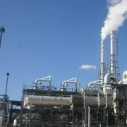
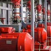
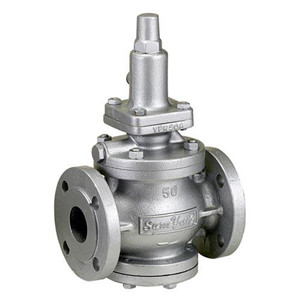
A steam pressure-reducing valve is an indispensable part of many steam systems. It plays a critical role by providing stable steam pressure and reduces the temperature to process applications in a process plant.

When the steam transmitted from the high-pressure boiler, the reducing valve control often used, which can reduce the size of the boiler and improve the steam dryness, convenient for long-distance transmission. Due to the high steam density at high pressure, the pipe with the same diameter can transport more high-pressure steam than low-pressure steam, thus reducing the size of the pipe and saving the cost.

Drain water valve

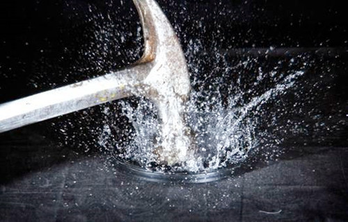
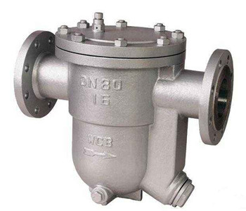
A steam trap is a kind of valve which can automatically remove condensed water and other non-condensing gas from the steam pipe and steam equipment and prevent steam leakage. The water to be discharged mainly comes from the condensate water at the bottom of the boiler cylinder, the condensate water at the bottom of the workshop cylinder, the condensate water of the steam separator before decompression and the condensate water of the conditioner sub-cylinder. According to its operation principle, there are mainly floating ball drain water valve, thermodynamic drain water valve, thermostatic drain water valve, inverted bucket drain water valve and so on.


In addition, you can also choose a gate valve and globe valves when the steam pipe temperature is less than 425℃. Gate valve is mainly used for steam pipeline where no need frequent open or closure; The globe valve offers a better function of flow regulation. Butterfly valve is not recommended to be used in steam pipeline, because the high pressure inside the valve, it’s difficult to switch  and the sealing surface is easy to damage, so it cannot be frequently switched, so the butterfly valve does not put up good performance as the gate valve; However, if the pipeline pressure is not very high (below 6.4 Mpa), it can also be used, but it is recommended to use metal hard seal butterfly valve because of the high temperature. You can choose the eccentric valve with a WCB material body, installation should pay attention to the flow direction, the pipeline should be kept clean to prevent the tight close.


In short, selection of valve for steam service depends on the purpose of the valve, pipe diameter, temperature and cost. As an industrial valve manufacturer,  any valve needs, call us today!

What metal material can be used for valve seal?

The valve seal is the key part to determine valve performance. The other factors like corrosion, friction, flash, erosion, oxidation, and ect should be considered when selecting sealing surface material. Valve seals are usually divided into two categories, one is a soft seal such as rubber (including butene rubber, fluoro rubber, etc.), plastic (PTFE, Nylon, etc.). The other is metal type hard seal, mainly including Copper alloy (for low pressure valves), Chromium stainless steel (for common and high pressure valves), Stellite alloy (for high temperature and high-pressure valves and strong corrosion valves), Nickel base alloy (for corrosive media). Today here we will mainly introduce the metal materials used in the sealing surface of the valve.


Copper alloy

Copper alloy offers better corrosion and abrasion resistance, suitable for the flow medium such as water or steam with PN≤1.6MPa, the temperature does not exceed 200℃. The sealed auxiliary structure is fixed on the valve body by surfacing and melting casting method. The commonly used materials are cast copper alloy ZCuAl10Fe3, ZCuZn38Mn2Pb2, etc.


Chromium stainless steel

Chrome stainless steel has good corrosion resistance and is usually used for water, steam and oil and the media of which temperature does not exceed 450℃. The sealing surface of Cr13 stainless steel is mainly used for gate valves, globe valves, check valves, safety valves, hard-sealed ball valves and hard-sealed butterfly valves made of WCB, WCC and A105 carbon steel.


Nickel base alloy

Nickel base alloys are important corrosion-resistant materials. Commonly used as sealing cover materials are: Monel alloy, Hastelloy B and C. Monel is the main material resistant to hydrofluoric acid corrosion, suitable for alkali, salt and acid solvent medium with a temperature of -240 ~ +482 ℃. Hastelloy B and C are corrosion-resistant materials in the sealing surface material of valve, suitable for corrosive mineral acid, sulfuric acid, phosphoric acid, wet HCI gas and strong oxidizing medium with a temperature of 371 ℃ (hardness of 14RC) and chlorine-free acid solution with a temperature of 538 ℃ (hardness of 23RC)


Carbide

Stellite alloy has good corrosion resistance, erosion resistance and abrasion resistance, suitable for different applications of the valve and temperature – 268 ~ + 650 ℃ in a variety of corrosive media, is a kind of ideal sealing surface material, mainly used in cryogenic valves (- 46 ℃ -254 ℃), high-temperature valve (valve working temperature 425 ℃ >, body material for WC6, WC9, ZGCr5Mo the wear resistance of the valve (including different working temperature level of wear resistance and erosion resistance of valve), sulfur resistance and high-pressure valve, etc. Due to the high price of Stellite alloy for surfacing. For the black water system and mortar system used in coal chemical gas production, the ball surface of the extremely hard wear-resistant ball valve is required to use the supersonic spray WC(Tungsten carbide) or Cr23C6(Chromium carbide).


We provide better sealing parts obtained from qualified hard metal material to the specific density required by valve applications. Call us today for your industrial valve demands!


Gate valves used for nuclear plant

Nuclear valve refers to the valves used in the Nuclear Island (NI), Conventional Island (CI) and auxiliary facilities, the balance of Nuclear Island (BOP) system of the power plant. These valves can be divided into class Ⅰ, Ⅱ, Ⅲ, non-nuclear according to its security requirements in sequence. Valves are the most used control equipment transporting flow media and the essential part of the nuclear power plant.

Nuclear Island is the core of a nuclear power plant where nuclear energy is converted into thermal energy, including the Nuclear Steam Supply System (NSSS) and Nuclear Island auxiliary facility (BNI). The NCI is the workhorses of nuclear power plants, where heat is converted into electricity (including steam turbines all the way to power output). The usage of valves in the three systems of NI, CI and BOP is 43.5%, 45%, and 11.5% respectively.

A pressurized water reactor nuclear power plant will need about 1.13 million NI valves, which can be divided into gate valves, globe valves, check valves, ball valves, butterfly valves, diaphragm valves, pressure relief valves and regulating (control) valves according to the types of valves. This section mainly introduces gate valves in nuclear safety (specification) classes Ⅰ and Ⅱ.

The diameter of gate valves for Nuclear Island is generally DN 80mm-350mm. Forgings are suggested; be used for gate valve bodies of class grade Ⅰ and castings are allowed for gate valve bodies of Nuclear class 2 and 3. However, forgings are often used because the casting quality is not easy to control and be guaranteed. The valve body and bonnet of the nuclear valve is usually flange connected, which adds a lip sealing welding process and makes the sealing more reliable. In order to prevent the leakage of the medium, the double layer packing belt is usually adopted, and the Disc spring pretension device is used to prevent the packing loosening. These gate valves can be driven manually or electrically. The influence of the rotational inertia of the motor on the closing force should be taken for electric transmission device of the electric gate valve. It is better to use the motor with a braking function to prevent overload.

According to its body structure, nuclear gate valve can be divided into wedge elastic single gate valve, wedge double gate valve, parallel double gate valve with spring pretension and parallel double gate valve with top block.

Wedge type elastic single gate valve is characterized by its reliable sealing seats and the angle matching between the sealing surface of gate and valve body is required, which is widely used in the main loop system of nuclear power plants. Wedge-type double-plate gate valve is a common valve in thermal power station, its wedge double-plate angle can be adjusted by itself, more reliable sealing and convenient maintenance.

A load of parallel double gate valve with spring preloading will not increase sharply when the gate is closed, but the gate never releases the valve seat made by the spring when it is opened and closed, which leading more sealing surface weariness. The top block parallel type double gate valve provides a more reliable sealing performance which using the top block to make the inclined plane of the two gates stagger to close the gate valve.

Gate valve without packing is also used in the nuclear island. The hydraulically operated gate valve that depends on its own pressurized water to push the piston to open or close the valve. The fully enclosed electric gate valve uses a special motor to operate the gate by means of an inner planet decelerating mechanism which is immersed in water. However, these two gate valves have the disadvantages of complex structure and high cost.


Generally speaking, the features of gate valves for nuclear islands should be:

1) Welded hydraulic double gate plate parallel gate valve with a nominal pressure PN17.5 Mpa, working temperature up to 315℃ and nominal diameter DN350~400mm.

2)Electric wedge-type double gate valve applied in light water coolant primary circuit would be nominal pressure PN45.0Mpa, temperature 500℃ and nominal diameter DN500mm.

3)Electric wedge-type double gate valve used in the primary road of nuclear power plant with graphite-moderated reactor should be nominal pressure PN10.0Mpa, nominal diameter DN800mm and operating temperature up to 290℃.

4) Welded connected electric elastic plate gate valve is adopted on steam and process water pipes of steam turbine plant with a nominal pressure pn2.5mpa, working temperature 200℃, nominal diameter DN100~800mm.

5)The double gate valve with diversion hole is used in the high power graphite-moderated boiling water reactor nuclear power plant. Its nominal pressure is PN8.0MPa while the opening or closing of the valve carried when the pressure drop is ≤1.0MPa.

6) Elastic plate gate valve with frozen sealing packing is ideal for fast reactor nuclear power plant.

7) Internal pressure self-sealing bonnet wedge-type double gate valve for water-hydro power reactor unit with nominal pressure pn16.0mpa and nominal diameter DN500mm.

8) Wedge-type double gate valves with butterfly springs on travel parts are normally bolted flanged and sealed welded.