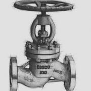
How many types of globe valve do you know?

The globe valve is designed with a stem that moves up and down to allow the medium flow one-way movement and make the sealing surface of the valve disc and seat tightly fit to prevent medium flow. It’s characterized saving elbow and operate conveniently and can be installed in the bent part of the pipeline system. There are various types of globe valve and designs, each with their own pros and cons. In this blog, we will introduce the classification of globe valves in details.


The flow direction of globe valve

  1. Tee shape/Split body globe valve
    The design making inlet and outlet channels of the valve are 180° in the same direction and has the lowest coefficient of flow and highest pressure drop. Tee/Split type globe valve can be used in severe throttling services such as in bypass line around a control valve.
  2. Y pattern globe valve
    Its disk and seat or the seat sealing an inlet/outlet passage present a certain angle, usually 45 or 90 degrees to the pipe axis. Its fluid hardly changes flow direction and has the least flow resistance in the globe valve types, suitable for coke and solid particles pipeline.

3. Angle pattern globe valves

Its flow inlet and outlet are not in the same direction with a 90° angle, which produces certain pressure drop. The angle globe valve is characterized by its convenience and without the use of an elbow and one extra weld.


Stem and disc of globe valves

  1. Outside screw stem stop valve
    The stem thread is outside of the body without connection with the medium to avoid the corrosion, easy to lubricate and operate.
  2. Inside screw stem stop valve
    The inner valve stem thread contact directly with the medium, easy to be corrosion and cannot be lubricated, usually used in the pipeline with the small nominal diameter and the medium working temperature is not high.
  3. Plug disc globe valve

Plug valve is also known as the plunger globe valve. With a radial sealing structure design, by the polished plunger on the two elastic sealing ring through the body and bonnet connection bolt applied on the bonnet load around the elastic sealing ring to achieve the sealing of the valve.

4. Needle globe valve

Needle globe valve is a kind of small diameter instrument valve, which plays the role of opening and closing and flows control in instrument measuring pipeline system.

5. Bellows globe valve

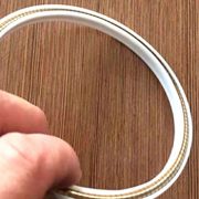
Formed stainless steel bellows design offers reliable sealing performance, suitable for flammable, explosive, toxic and harmful media occasions, can effectively prevent leakage.


Applications of globe valves

  1. PTFE-Lined globe valve
    PTFE Lining globe valve is the valve that molding(or inset) Polytetrafluoroethylene resin in the inner wall of the metal valve pressure piece (the same method applies to all kinds of pressure vessels and pipe accessories lining) or the outer surface of the valve inner piece to resist the strong corrosive medium of the valve. PTFE lined globe valve is applicable to Aqua regia, sulfuric acid, hydrochloric acid and various organic acids, strong acids, strong oxidants at various concentrations of -50 ~ 150℃, as well as strong alkali organic solvent and other corrosive gases and liquid medium in the pipeline.
  2. Cryogenic globe valve
    Cryogenic globe valves usually refer to valves operating below -110℃. It is widely used in liquefied natural gas, petroleum and other low-temperature industries. At present, the globe valve with an applicable temperature of -196℃ can be manufactured, which uses liquid nitrogen for low-temperature pretreatment to completely avoid sealing deformation and leakage.

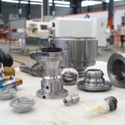
PERFECT manufacture and supply globe valves according to ANSI and API standards, the valve disc and seat sealing surface are made of stellite cobalt carbide surfacing that offering various advantages like reliable sealing, high hardness, wear resistance, high-temperature resistance, corrosion resistance, abrasion resistance and long service life. We design each valve according to the flow parameters presented. Contact our sales representative for details.

A collection of API valve standards

In the United States institutions system, there are several standards can be used to specify the industrial valve like ASME standard ( American Society of Mechanical Engineers), API standard (American Petroleum Institute), ANSI standard (American National Standards Institute), MSS SP standard (Manufacturers Standardization Society of the Valve and Fittings Industry). Each of them has specific specifications for valves and complements each other, here we collect a series of commonly used valve API standards for general industrial valves.


API 6A Specification for wellhead and Christmas tree equipment
API 6D specification for pipelines and pipe valves
API 6FA: The standard for Fire Test for Valves
API 6FC Fire Test for Valve with Automatic Backseats.
API 6FD Specification for fire test for check valves.
API 6RS Referenced Standards for Committee 6, Standardization of Valves and Wellhead Equipment.
API 11V6 Design of Continuous Flow Gas Lift Installations Using Injection Pressure Operated Valves.
ANSI/API RP 11V7 Recommended Practice for Repair, Testing, and Setting Gas Lift Valves.
API 14A Specification for subsurface safety valve equipment
API 14B Design, installation, operation, test and redress of the subsurface safety valve system.
API 14H Recommended practice for installation, maintenance and repair of surface safety valves and underwater safety valves offshore
API 520-1 Sizing, Selection, and Installation of Pressure-Relieving Devices in Refineries: Part I – Sizing and Selection.
API 520-2 Recommended Practice 520: Sizing, Selection, and Installation of Pressure-Relieving Devices in Refineries-Part II, Installation.
API 526 Flanged Steel Pressure Relief Valves.
API 527 Seat Tightness of Pressure Relief Valve.
API 553 Refinery Control Valve
API 574 Inspection of Piping, Tubing, Valves, and Fittings
API 589 Fire test for the evaluation of valve stem packing
API 591 Process valve qualification procedure
API 594 Check valves: Flanged, lug, wafer and butt welding
API 598 Valve Inspection and Testing.
API 599 Metal Plug Valves – Flanged and Welding Ends
API 600 Steel gate valves – Flanged and butt-welding ends, bolted bonnets
API 602 Gate, globe, and check valves for size and DN100(NPS 4) and smaller for the petroleum and natural gas industries.
API 603 Corrosion-resistant, Bolted Bonnet Gate Valves—Flanged and Butt-welding Ends
API 607 Fire test for quarter-turn valves and valves equipped with nonmetallic seats
API 608 Metal Ball Valves-Flanged, Threaded and Butt-Welding Ends
API 609 Butterfly valves: Double flanged, lug and wafer type
API 621 Reconditioning of Metallic Gate, Globe, and Check Valves


Which actuator controller is better for valve? Electric or pneumatic?

Valve actuators refer to devices that provide linear or rotary movement of the valve, which using liquid, gas, electricity or other energy sources and converted it by motors, cylinders or other devices.

Pneumatic actuator uses air pressure to realize the valve drive open and close or regulation with one piece implementation and regulation mechanism, can be divided into the membrane, piston and rack and pinion pneumatic actuator. The pneumatic valve structure is simple, easy to operate and check, can also easily achieve the positive reaction of the exchange, more economical than electric and hydraulic. It is widely used in power plant, chemical industry, oil refining and other production processes with high safety requirements.

Electric actuator has a large torque, simple structure and easy to maintenance, can be used to control air, water, steam and corrosive media like mud, oil, liquid metal, radioactive media and other types of fluid flow. It also has good stability, constant thrust and good anti-deviation ability. Its control accuracy is higher than the pneumatic actuator and can well overcome the imbalance of medium, mainly used in power plants or nuclear power plants.

When selecting a valve actuator, it is necessary to know the type of valve, torque size and other issues. Generally in the term of the structure, reliability, cost, output torque and other terms to consider. Once the actuator type and the drive torque required for the valve are determined, the actuator manufacturer’s data sheet or software can be used for selection. Sometimes the speed and frequency of valve operation should be considered. Here we collect some tips or suggestion for the actuators  choices:

Cost
The pneumatic actuator must be used together with valve positioner and air source, and its cost is almost the same as the electric valve. In water and sewage treatment, most valve actuators are operated in on/off mode or manually. The monitoring functions of electric actuators, such as overtemperature monitoring, torque monitoring, conversion frequency and maintenance cycle, must be designed in the control and test system, which leads to a large number of line input and output. In addition to terminal position sensing and air source handling, pneumatic actuators do not require any monitoring and control functions.

Security
Electric valves are an electric power source, circuit board or motor failure prone to spark, generally used in the environmental requirements are not high occasions. Pneumatic actuators can be used for potentially explosive occasions, and it is worth noting that the valve or valve island should be installed outside the explosion area, the pneumatic actuators used in the explosion area should be driven by trachea.

The service life
The electric actuators are suitable for intermittent operation, but not for continuous closed-loop operation. Pneumatic actuators have excellent overload resistance and are maintenance-free, requiring no oil change or other lubrication, with a standard service life of up to one million switching cycles, which is longer than other valve actuators. In addition, pneumatic components with high vibration resistance, corrosion resistant, strong and durable, even not damage at a high temperature. Electric actuators consist of a large number of components and are relatively easy to damage.

Response speed
Electric actuators run slowly than pneumatic and hydraulic actuators, it takes a long time from the regulator output signal to response and movement to the corresponding position. There is a great loss of energy when the supplied energy is converted into motion. Firstly, the electric motor converts most of the energy into heat, and then it uses gears with a complex structure. Frequent regulation will easily cause the motor to overheat and generate thermal protection.

Essentially, the main difference between electric and pneumatic valves is the use of actuators and has nothing to do with the valve itself. Choose which actuator to use that depends on the operating conditions, such as a chemical application or explosion protection or wet environment where need pneumatic valve and an electric valve is ideal for large diameter piping system.

What’s the advatages of PEEK valve seats?

PEEK (Polyetheretherketone) was developed by ICI (British chemical industry corporation) in 1978. Subsequently, it was also developed by DuPont, BASF, Mitsui optoelectronic co., LTD., VICTREX and Eltep (United States). As a kind of high-performance polymer material, PEEK is characterized by low creep variable, high elastic modulus, excellent wear resistance and corrosion resistance, chemical resistance, non-toxic, flame retardant, still maintain good performance even at high temperature/pressure and high humidity under the poor working conditions, can be used for high temperature and high-pressure valves, nuclear valves, pump compressor valve plates, piston rings, valve and the core of the sealing parts. Why PEEK valves are so popular that depends on PEEK’s excellent characteristics.

High temperature resistant
PEEK resin offers a high melting point (334℃) and glass transition temperature (143 ℃). Its continuous use temperature can be up to 260℃and load thermal transformation temperature of 30%GF or CF reinforced brand is up to 316℃.

Mechanical properties
PEEK raw material resin has good toughness and rigidity, and it has excellent fatigue resistance to alternating stress comparable to alloy materials.

Flame retardant: flammability of materials, which is specified in standards UL94, is the ability to maintain combustion after being ignited with high energy from oxygen and nitrogen mixtures. First, a vertical sample of a certain shape is ignited, and then measured the time taken by the material to automatically extinguish. PEEK test results are v-0, which is the optimal level of flame retardancy.

Stability: PEEK plastic materials have superior dimensional stability, which is important for some applications. The environmental conditions such as temperature and humidity have little impact on the size of PEEK parts which can meet the requirements of high dimensional accuracy.

  1. PEEK plastic raw material has a small shrinkage in injection molding, which is beneficial to control the dimensional tolerance range of PEEK injection parts, making the dimensional accuracy of PEEK parts much higher than that of general plastics;
  2. Small coefficient of thermal expansion. The size of PEEK parts changes little with the change of temperature (which may be caused by the change of ambient temperature or friction heating during operation).
  3. Good dimensional stability. The dimensional stability of plastics refers to the dimensional stability of engineering plastics in the process of usage or storage. This dimensional change is mainly due to the increase of activation energy of polymer molecules caused by some degree of a crimp in the chain segment.
  4. Outstanding thermal hydrolysis performance. PEEK is low in water absorption under high temperature and humidity. No obvious change in size caused by water absorption of common plastics like Nylon.

PEEK was developed in just two decades, has been widely used in oil and gas, aerospace, automotive manufacturing, electronics, medical and food processing and other fields. In the oil and gas industry, PEEK’s exceptional performance makes it ideal for use as a primary sealing part.

The PERFECT company manufactured and supplied industrial valve with PEEK soft seats and we strive to provide with high-quality, specialty valves as quickly and efficiently as possible. Whatever it is you are looking for, PERFECT will help you to find the appropriate product in the suitable application.

Plug valve VS ball valve

Plug valve with one piece top -entry design has a lot of similarities with a one piece top – entry ball valve. Strictly speaking, ball valve and plug valve are the same types of valve due to their similar function and characteristics and both of them have a very wide range of applications. Today we will introduce the difference of plug valve and ball valve.

Plug valve also known as cock valve, rotating plug valve, is a kind of oldline valve. The valve “plug” (mostly conical or cylinder) combined and the body of the conical hole surface of the sealing, to move depending on the plug body around the center line of the valve to achieve open and close. It is mainly used for cutting, distribution and change the flow of media. The plug valve is simple in structure and small in size. It can be opened and closed by only 90% rotation. It is widely used in a low pressure, small diameter and medium or low-temperature occasions. Plug valve sealing surface is easy to wear, also easy to get stuck in the occasion of high temperature or high pressure, not suitable for flow regulating.

The ball valve is evolved from the plug valve with a ball as its closing parts, it around the center of the valve to achieve the opening and closure, mainly used to cut off, distribution and change the flow direction of the medium. Ball valves can close tightly just 90 degrees of rotation or a small torque. Full horizontal of the valve body cavity provides little resistance, through the flow path for the medium. The main characteristics of the ball valve are compact structure, easy to operate and maintenance, suitable for water, solvent, acid and natural gas and other general media, also suitable for working conditions of harsh media, such as oxygen, hydrogen peroxide, methane and ethylene. The ball valve body can be one piece, can also be combined. It is generally considered that ball valves are most suitable for opening and closing directly, but recent developments have designed them for throttling and flow control.


Plug valve VS ball valve

Different principle

The ball valve is evolved from the plug valve. They have the same 90-degree rotation operation, but depends on the “plug” is a plug or a ball with a circular through hole or channel passing through its axis. The ball and the ports should look like this: when the sphere rotates by 90 degrees, it will appear as a sphere at the inlet and outlet to cut off the flow. For the plug valve, the conical plug and the body surface formed by the conical pressure, the upper parts are sealed with packing 
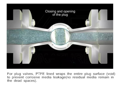
between the plug and the gap between the body. Plug valve is simple and often economical because it usually does not have bonnets, but the handle exposed outside at the end instead.

Different application

Plug valves offer better performance in the term of cutting than ball valves, but that doesn’t show obviously. The sealing surface of the plug valve is much larger than the ball valve and supplies a better sealing effect, but a greater torque and small diameter. The ball valve is ideal for switching pipeline medium, not as a throttle valve to avoid the valve long time by medium erosion and loss of tightness. Now the sealing effect of the ball valve has been greatly improved with the progress of the sealing technology, so we can say that the plug valve is used for the sealing requirements are strict but the diameter is not large, and the ball valve is used for the sealing effect is not too strict and the diameter is large.

Plug valve is lower cost

For the plug valve, the “plug” is completely covered by the bushing, making the valve body and plug free from wear. Replacement of the bushing and top seal can complete the repair and update of the valve, which can meet the long-term service requirements of 300℃. This has considerable competitive advantages over other hard-sealed metal ball valves in this temperature range. In addition, the plug valve processing area only is the top face and flange, other parts all one-step casting molding and the internal body need no processing. Compared with the ball valve, it offers low processing allowance, when making the INCONEL, MONEL, HAST alloy and other special materials as its materials, plug valve has an obvious price advantage.

What’s the difference between metal seat valves and soft seat valves?

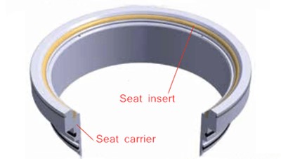
When choosing an industrial valve, you will face numerous choices. Available materials, proper size, and design (1, 2, or 3 pieces, end connections, etc.) are the key factors to decide which type of valve to use. Equally important is the type of valve seats which directly determines the leakage class of the valve. Before you choose the right valve seats, you must know the following question: Is the medium corrosive? Contains abrasive particles? For high temperature or high pressure? Once you know these things, you will make the right choice. Therefore, the first step to fully understand your craft condition: choose a suitable valve seat.

Almost all the industrial valves are metal seat and soft seat available. Both of them offers excellent sealing performance and have their unique and irreplaceable advantages, and inevitably, due to the shortcomings, costs, abrasion resistant performance, working conditions of different materials, metal-seated valves and soft-seated valves both have their markets and long-lasting solutions for critical applications. The table below showed the advantages and disadvantages of metal seat valves and soft seat valves.

Metal seat VS soft seat:

Valves Metal seat Soft seat
Material Copper alloy (for low-pressure valves);

Chrome stainless steel (for medium and high-pressure valves);

Satellite Seat Surface (High temperature and pressure valves and highly corrosive valves);

Nickel-based alloys (for corrosive media);

Metal-ceramic sealing material, etc

The elastic nonmetallic material such as PTFE(Temperature -50°F to 400°F);

modified PTFE( Temperature -50°F to 450°F);

Delrin(High pressure up to 5000psi dependant on valve size and temperature range of -50°F to 180°F);

Nylon(Temperature rating -30°F to 200°F;

PEEK(Temperature -70°F to 550°F);

Manufacturing  process


Need grinding, hardening and other precision processing. High precision requirements, complex processing and long production cycle Easy deformation, low processing accuracy, even free-processing
Medium


Hot water, gas, gas, oil, acid and alkali medium Air, water and other non-corrosive media
Working pressure Medium or high pressure above 3.5mpa Medium or low pressure
Working  temperature


Metal seated valves are suitable for temperature up to 540℃ (Higher based on the material of body and trim). Soft seated ball valves are suitable for the working temperature lower than 260℃. Aging easily affected by temperature, used in room temperature environment. Fire protection is needed to prevent leakage at high temperatures.
Leakage class(Ball valve) Class V and VI VI
Cost & Price Metal seat valve is much higher than soft seat valves Cheaper than metal seat valves
Sealing performance Wear resistance but easy to leak relatively poor sealing performance Easy to wear and can achieve a high level of sealing performance or even zero leakage