What’s mud valve?

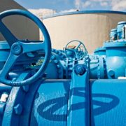
Mud valve is a type of angel- globe valve controlled by a hydraulic actuator, used in sedimentation tank bottom for city water or sewage treatment plant sludge and wastewater discharge. The medium for mud valve is primary sewage less than 50℃ and its working depth is less than 10 meters. The mud valve is for low-pressure applications only and composed of the valve body, actuator, piston, stem and disc, which also can be controlled by the solenoid valve from a distance.

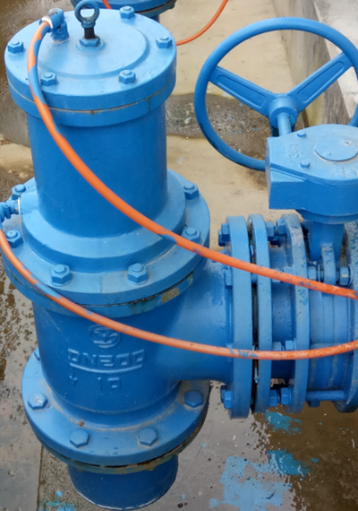
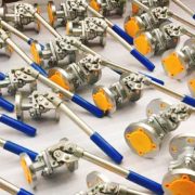
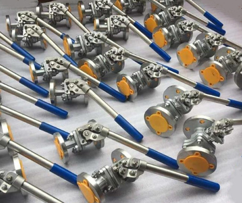
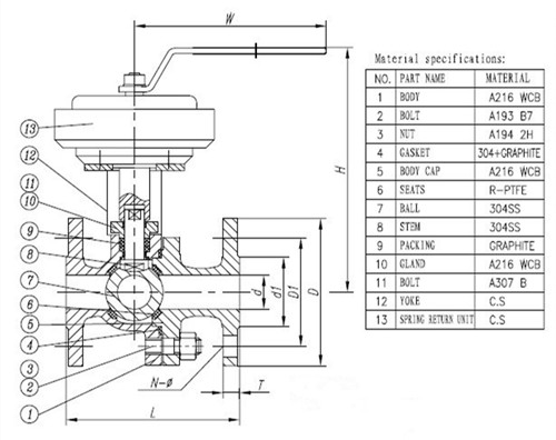
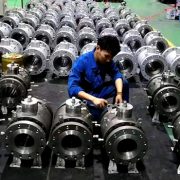
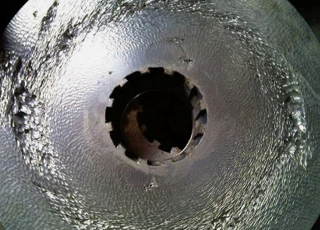
The mud valve supplied by PERFECT CONTROL is made by cast iron body, cover, and yoke, bronze seats with a resilient seat which forms a bubble-tight seal that won’t leak, even when minor debris obstructs the valve. The stainless steel stem is to prevent corrosion from years of submerged services. Mud valve can be generally divided into hydraulic mud valve and pneumatic angle mud valve according to the actuator. Double chamber diaphragm drive mechanism to replace the piston without movement wear. The hydraulic cylinder drive disc lift valve body channel open or closed to achieve fluid on and off.

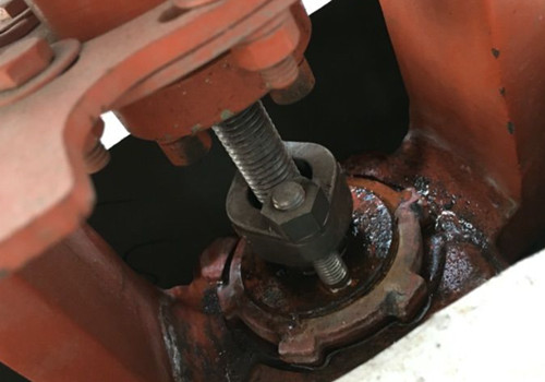
The mud valve offers a lot of advantages: Cover with screw can be directed by the handle for shallow water; Tin-bronze sealing surface offers good corrosion resistance and better wear-resistant or use in submerged installations; The cast iron coating is corrosion resistant and safe for potable water applications; Hydraulic relief slots of plug stem allows any sludge to drain out so your valve won’t jam.

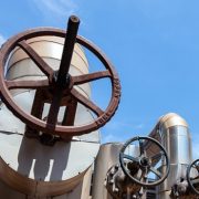
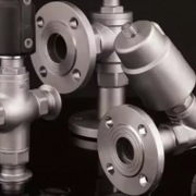
The mud valve is installed in the place where the discharge of sediment in the pipeline and the discharge of sewage during maintenance is needed, that is, the discharge tee at the lowest position of the pipeline and tangent to the sewage flow, and the impact of sewage erosion on the accessories shall be considered.

What’s spring return ball valve?

Spring return valve refers to the valve that can return to the original starting position under the action of internal spring. It is suitable for 1/4 rotary handle operation of the ball valve, is generally composed of two/three pieces of the ball valve and a spring lever or handles unit to return the valve to the fully open position, also known as spring automatic return ball valve or spring self-closing ball valve. The spring return ball valves can be offered to include socket weld, butt weld and flanged, they are used in applications where positive return to the closed position is required following momentary or short periods of operation for food, pharmaceutical, oil, chemical, metallurgical, mechanical process and other industries. In addition, the spring return design has been used for gate valves and globe valves.


Details of the spring return ball valve

Size: Up to DN50

Pressure: Up to Class 600

Standards: API 608/API 6D

Test standards: API 598

Nominal diameter: DN15 — DN100 (mm)

Connection: Thread, flanged

Temperature range: ≤-180℃

Body material: Cast steel WCB, Stainless steel 304/316


Features

  • Manual back to started position quickly and avoiding the wrong operation;
  • Two-piece or three-piece structure is simple and easy to maintain, full port and low flow resistance.
  • Stainless steel ball material, reduce the parts wearing and extend the service life.
  • PTFE seat/packing rod offers good sealing performance, not easy to be medium corrosion or friction damage when fully opened or fully closed.


The commonly used material for valve body

Meets the preceding text, the common material of valve body includes carbon steel, low-temperature carbon steel, alloy steel, Austenitic stainless steel, cast copper-alloy titanium alloy, aluminum alloy, etc., of which carbon steel is the most widely used body material. Today here we will collect the commonly used material for valve body.

Valve body material Standards Temperature /℃ Pressure /MPa Medium
Gray cast iron -15~200 ≤1.6 Water, gas,


Black malleable iron -15~300 ≤2.5 Water, seawater, gas, ammonia


Ductile iron -30~350 ≤4.0 Water, seawater, gas, air, steam


Carbon steel (WCA、WCB、WCC) ASTM A216 -29~425 ≤32.0 Non-corrosive applications, including water, oil and gas
Low-temp carbon steel (LCB、LCC) ASTM A352 -46~345 ≤32.0 Low temp application
Alloy steel (WC6、WC9)

(C5、C12)

ASTM A217 -29~595

-29~650

High-pressure Non-corrosive medium /

Corrosive medium

Austenitic stainless steel ASTM A351 -196~600 Corrosive medium
Monel alloy ASTM A494 400 Medium containing hydrofluoric acid
Hastelloy ASTM A494 649 Strong corrosive media such as dilute sulfuric acid
Titanium alloy A variety of highly corrosive media
Cast copper alloy -273~200 Oxygen, seawater
Plastics and ceramics ~60 ≤1.6 Corrosive medium


Codes Material Standards Applications Temperature
WCB Carbon steel ASTM A216 Non-corrosive applications, including water, oil and gas -29℃~+425℃
LCB Low-temp steel ASTM A352 Low temp application -46℃~+345℃
LC3 3.5%Ni- steel ASTM A352 Low temp application -101℃~+340℃
WC6 1.25%Cr0.5%Mo steel ASTM A217 Non-corrosive applications, including water, oil and gas -30℃~+593℃
WC9 2.25Cr
C5 5%Cr 0.5%Mo ASTM A217 Mild or noncorrosive applications -30℃~+649℃
C12 9%Cr 1%Mo
CA15(4) 12%Cr steel ASTM A217 Corrosive applications +704℃
CA6NM(4) 12%Cr steel ASTM A487 Corrosive applications -30℃~+482℃
CF8M 316SS ASTM A351 Corrosive, ultra-low or high temp non-corrosive applications -268℃ to+649℃,425℃ above or specified carbon content is 0.04% or above
CF8C 347SS ASTM A351 High temp,corrosive applications -268℃to+649℃,540℃ above or specified carbon content is 0.04% or above
CF8 304SS ASTM A351 Corrosive, ultra-low or high temp non-corrosive applications -268℃to+649℃,425℃  above or specified carbon content is 0.04% or above
CF3 304LSS ASTM A351 Corrosive or non-corrosive applications +425℃
CF3M 316LSS ASTM A351 Corrosive or non-corrosive applications +454℃
CN7M Alloy stel ASTM A351 Good corrosion resistance to heat sulfuric acid +425℃
M35-1 Monel ASTM A494 Weldable grade, good resistance to organic acid and saltwater corrosion.

Most alkaline solution corrosion resistance

+400℃
N7M Hastelloy B ASTM A494 Suitable for various concentrations and temperatures of hydrofluoric acid, good resistance to sulfuric acid and phosphoric acid corrosion performance +649℃
CW6M Hastelloy C ASTM A494 At high temperature, it has high corrosion resistance to formic acid, phosphoric acid, sulfurous acid and sulfuric acid +649℃
CY40 Inconel ASTM A494 Works well in high temp applications, has good corrosion resistance to highly corrosive fluid media


As a fully stocked manufacturer and distributor of the industrial valve, PERFECT provides a complete line of valves for sale that is supplied to various industries. Available valve body material including carbon steel, stainless steel, titanium alloy, copper alloys, etc and we make the material easy to find for your valve need.


Control valve seat leakage class

In past articles, we introduce “What caused the leakage of valve” and “The leak rates standards of the industrial valve”, today here we will continue to discuss the valve leakage class and classification.

ANSI FCI 70-2 is an industry standard for control valve seat leakage, specified six leakage classes (Class I, II, III, IV, V, VI) for control valves and defines the test procedure, and superseding ANSI B16.104. The most commonly used are CLASS I, CLASS IV and CLASS Vl. Metal-elastic seal or metal seal should be selected in engineering design according to the characteristics of the medium and the opening frequency of the valve. Metal seated valve seal grades should be is stipulated in the order contract, the rates I, Ⅱ, Ⅲ is used less due to request a lower level, generally choose Ⅳat least and V or Ⅵ for higher requirements.


Classifications of control valve seat (ANSI/FCI 70-2 and IEC 60534-4)

Leakage class Maximum leakage allowable Test medium Test pressure Test rating procedures Valve type
Class I / / / No test required Metal or resilient seated valves
Class II 0.5% of rated capacity Air or water at 50-125 F (10-52C) 3.5 bar, operating differential whichever is lower Lower of 45 to 60 psig or maximum operating differential Commercial double-seat control valves or balanced single-seat control valves with a piston ring seal and metal-to-metal seats.
Class III 0.1% of rated capacity As above As above As above Same as class II, but a higher degree of seat and seal tightness.
Class IV 0.01% of rated capacity As above As above As above Commercial unbalanced single-seat control valves and balanced single-seat control valves with extra tight piston rings or other sealing means and metal-to-metal seats.
Class V 0.0005 ml per minute of water per inch of port diameter per psi differential Water at 50-125F (10-52C) Max service pressure drop across valve plug, not to exceed ANSI body rating. Maximum service pressure across valve plug not to exceed ANSI rating Metal seat, unbalanced single-seat control valves or balanced single-seat designs with exceptional seat and seal tightness
Class VI Not to exceed amounts shown in following table based on port diameter. Air or nitrogen at 50-125 F (10-52C) 3.5 bar(50 psig) or max rated differential pressure across valve plug whichever is lower. Maximum service pressure across valve plug not to exceed ANSI rating Resilient seating control valves either unbalanced or balanced single-seat with “O” rings or similar gapless seals.


What caused the leakage of valve?

Valves are one of the main leakage sources in the pipeline system of the petrochemical industry, so it’s critical to the leakage of valves. Valve leakage rates are actually the valve sealing level, valve sealing performance is referred to as the valve sealing parts to prevent the ability of media leakage.

The main sealing parts of the valve including the contact surface between the opening and closing parts and the seat, the fitting of packing and stem and packing box, the connection between the valve body and the bonnets. The former belongs to internal leakage, which directly affects the ability of the valve to cut off the medium and the normal operation of the equipment. The last two are external leakage, that is, media leakage from the inner valve. The loss and environmental pollution caused by external leakage are often more serious than that caused by internal leakage. Then do you know what caused the valve leakage?

Casting and forging valve body

The quality defects formed in the casting process such as sand holes, sand, slag holes and pores, and the forging quality defects like cracks and folds, both can cause leakage in the valve body.

Packing

The sealing of the stem part is the packing in the valve, that is designed to prevent gas, liquid and other media leakage. valve leakage will be caused by the deflection of gland fastening, improper packing bolt fastening, too little packing, wrong packing material and improper packing installation method in the installation process of packing.

Sealing ring

Incorrect or inappropriate seal ring material, poor surfacing welding quality with body; loose thread, screw and pressure ring; seal ring mounting, or use of a defective seal ring that was not found in the pressure test, resulting in valve leakage.

Sealing surface

Rough grinding of sealing surface, deviation of assembly of valve stem and closing part, improper quality selection of sealing surface material will cause leakage of the contact part between the sealing surface and valve stem.


In general, external leakage of valves is mainly caused by the poor quality or improper installation of the cast body, flange, and packing. Internal leakage often occurs in three parts: open and close parts and seat sealing surface of the joint, valve body and bonnet joint, valve closed position.

In addition, improper valve types, medium temperature, flow, pressure, or valve switch can not be fully closed, which will also cause valve leakage. Valve leakage is not allowed especially for high temperature and pressure condition, flammable, explosive, toxic or corrosive media, so the valve must provide reliable sealing performance to meet the requirements of its use conditions on the leakage.

How to prevent valve cavitation?

The disc and seat and other parts of the internal of the control valve and the reducing valve will appear friction, groove and other defects, most of these are caused by cavitation. Cavitation is the whole process of bubble accumulation, movement, division and elimination. When the liquid passes through the valve partially open, the static pressure is less than the saturation pressure of the liquid in the area of increasing velocity or after the valve is closed. At this time, the liquid in the low-pressure area begins to vaporize and produces small bubbles that absorb impurities in the liquid. When the bubble is carried to the area of higher static pressure by the liquid flow again, the bubble suddenly bursts or explodes, we call this kind of hydraulic flow phenomenon valve cavitation.

The direct cause of cavitation is flashing caused by a sudden change of resistance. Flashing refers to the high pressure of the saturated liquid after decompression into a part of the saturated steam and saturated liquid, bubble and the formation of smooth friction on the surface of the parts.

When the bubbles burst during cavitation, the impact pressure can be up to 2000Mpa, which greatly exceeds the fatigue failure limit of most metal materials. Bubble rupture is the main source of noise, the vibration produced by it can produce up to 10KHZ of noise, the more bubbles, the noise is more serious, in addition, cavitation will reduce the bearing capacity of the valve, damage valve inner parts and prone to produce leakage, then how to prevent valve cavitation?


  • Multiple-stage pressure reducing

Multistage step-down internal parts, that is, the pressure drop through the valve into several smaller, so that the pressure vena contraction section is greater than the steam pressure, to avoid the formation of steam bubbles and eliminate cavitation.


  • Increase the hardness of the material

One of the main causes of valve damage is that the material hardness can not resist the impact force released by the bubble burst. Surfacing or spray welding of stryker alloy based on the stainless steel to form a hardened surface, once damaged, a second time surfacing or spray welding can extend its service life of the equipment and reduce the maintenance cost.


  • Porous throttling design

Special seat and disc structure make the flow of liquid pressure higher than the saturated vapor pressure, the concentration of injection liquid in the valve of the kinetic energy into heat energy, thus reducing the formation of air bubbles.

On the other hand, making the bubble burst in the center of the sleeve to avoid the damage directly on the surface of the seat and disc.