The ceramic valves for chlorine application

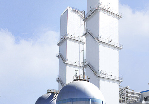
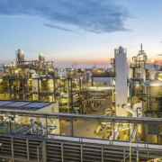
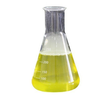
Liquid chlorine is a highly toxic and corrosive yellow-green liquid with a boiling point of -34.6 ℃ and a melting point of -103 ℃. It vaporizes into gas under normal pressure and can react with most substances. Electrolytic chlorine gas has a high temperature (85℃) and contains a large amount of water. After cooling and drying and liquefied by pressure cooling, of which process the volume is greatly reduced for storage and transportation. The liquid chlorine filling process is a production process designed for long-distance transportation, which may cause production hazards such as leakage, explosion, poisoning, etc. Besides, the working conditions of high pipeline pressure, low temperature, and negative pressure in the vacuum pumping stage, which have high requirements on the type and material of the valve.

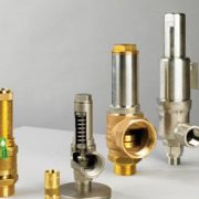
The characteristics of chlorine require the valve not only simple structure, small volume, lightweight and the drive torque is small, easy to operate quickly, and also has good sealing and excellent corrosion resistance. Part of the liquid chlorine vaporization because the valve outlet pressure is lower than the inlet during the liquid chlorine filling process, this process absorbs heat, making the valve temperature lower than the pipe, resulting in frost formation. In addition, the valve in the harsh environment has a high replacement frequency, which is not conducive to the safety of the entire equipment operation and maintenance costs. Most of the metal sealing valve’s chlorine corrosion resistance is limited while lined PFA/PTFE valve is a good choice, but a long time running lined PFA/PTFE valve will increase torque and cause aging, the practice has proved that the ceramic ball valve in the liquid chlorine working conditions supply a good performance.

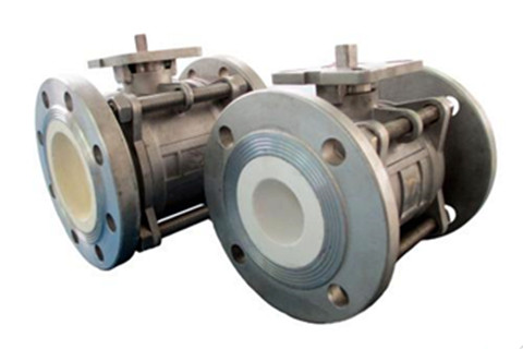
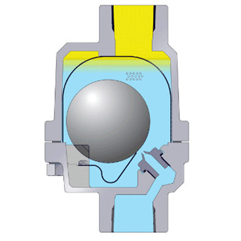
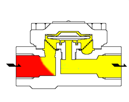
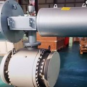
Pneumatic lined ceramic ball valve

The pneumatic ceramic ball valve consists of a limiter, solenoid valve, filter valve, ceramic ball valve and air path, etc. The roughness of the ceramic ball valve O-ball core and seat sealing surface can reach less than 0.1 m, making its sealing performance is higher than the metal ball valve, self-abrasive and small opening and closing torque. The port of lined ceramic can be completely separated from the metal part of the valve body, has been widely used corrosive and purity requirements of the medium.。


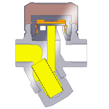
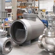
Electric V-type ceramic ball valve

The electric v-type ceramic regulating ball valve is composed of an electric actuator and a V-type ball valve. There is shear action between the v-shaped ball and the seat, and the ball still provides good sealing when the medium contains fiber or solid particles. The high-quality ceramic spool has high anti-abrasion performance, seat sealing ring can prevent the flow of direct erosion of the seat, extended seat life. The ceramic inner part can completely isolate the entire flow path, thus preventing the contact between the medium and the metal body, which can effectively prevent the corrosion of corrosive medium on the valve metal.


More information about ceramic ball valve or ceramic lined ball valve for sale, Contact us now!


How to choose the steam trap?

In the last article, we discuss what’s the steam trap, as we know, the steam trap is a type of self-contained valve which automatically drains the condensate from a steam containing enclosure while remaining tight to live steam, or if necessary, allowing steam to flow at a controlled or adjusted rate. Steam trap has the ability to “identify” steam, condensate and non-condensable gas to prevent steam and drains the water, which depending on the density difference, temperature difference and phase change, it can be divided into a mechanical steam trap, thermostatic steam trap and thermal dynamic steam trap.


The mechanical steam trap uses the change of condensate level to make the float ball rise (fall) to drive the disc to open (close) to prevent steam and discharge water due to the density difference between condensate and steam. The small undercooling degree makes the mechanical steam trap not affected by the working pressure and temperature changes and makes the heating equipment to achieve the best heat transfer efficiency, no water vapor storage. The maximum backpressure ratio of the trap is 80%, which is the most ideal trap for production process heating equipment. Mechanical traps include free-floating ball trap, free half floating ball trap, lever floating ball trap, inverted bucket type trap, etc.


Free-floating steam trap

A free-floating steam trap is that the floating ball rises or falls according to the water condensation with the water level due to the principle of buoyancy, it automatically adjusts seat hole open degree of continuous discharge condensate, when water stops into the ball back to the closed position and then drainage. The drain valve seat hole is always below the condensation water form a water seal, water and gas separation without leakage of steam.


Thermostatic steam trap

This kind of steam trap is caused by the temperature difference between the steam and condensate water temperature element deformation or expansion to drive valve core open and close. The thermostatic steam trap has a large degree of undercooling, generally 15 to 40. It uses heat energy to make the valve always has high-temp condensate water and no steam leakage, has been widely used in steam pipeline, heat pipeline, heating equipment or small heating equipment with low-temperature requirements, is the most ideal type of steam trap. The type of thermo-static steam trap includes diaphragm steam trap, bellows steam trap, bimetal plate steam trap and etc.


Diaphragm steam trap

The main action element of the diaphragm trap is the metal diaphragm, of which is filled with vaporization temperature that is lower than the saturation temperature of water liquid, generally the valve temperature is lower than the saturation temperature of 15℃ or 30℃. Diaphragm trap is sensitive to response, resistance to freezing and overheating, small size and easy to install. Its backpressure rate is more than 80%, cannot condense gas, long service life and easy maintenance.


Thermal steam trap

According to the phase change principle, the thermal power steam trap by steam and condensate water through the flow rate and volume changes of different heat so that the valve plate produced different pressure difference, that drives the valve plate switch valve. It is powered by steam and loses a lot of steam. It‘s characterized by simple structure, good water-resistant. With a maximum back of 50%, noisy, valve plate work frequently and short service life. The type of thermal power steam trap includes the thermodynamic (disc) steam trap, pulse steam trap, hole plate steam trap and so on.


Thermodynamic (disc) steam trap

There is a movable disc in the steam trap which is both sensitive and actuating. According to the steam and condensate when the flow rate and volume of different thermodynamic principles, so that the valve plate up and down to produce different pressure differential drive valve plate switch valve. The steam leakage rate is 3%, and the undercooling degree is 8℃-15℃. When the device starts, the cooling condensate appears in the pipeline and pushes off the valve plate by the working pressure to discharge rapidly. When the condensate is discharged, the steam is then discharged, the volume and flow rate of the steam is larger than the condensates, so that the valve plate produces pressure difference to close quickly due to the suction of the steam flow rate. When the valve plate is closed by pressure on both sides, the stress area below it is less than the pressure in the steam trap chamber from the steam pressure above, the valve plate is closed tightly. When the steam in the steam trap chamber cools to condense, the pressure in the chamber disappears. Condensate by working pressure to push the valve plate, continue to discharge, circulation and intermittent drainage.

Tips for safety valve installation

The safety valve is widely used in a steam boiler, LPG tanker, oil well, high-pressure bypass, pressure pipeline, pressure vessel of steam power generation equipment, and etc. The safety valve is closed under the action of external force on the opening& closure parts and when the pressure of the medium in the equipment or pipeline exceeds the specified value, it opens and drains the medium out of the system to protect the safety of the pipeline or equipment.

The safety valve shall be installed upright and as close as possible to the protected equipment or piping. If not installed nearby, the total pressure drop between the pipe and the safety valve inlet should not exceed 3% of the valve’s constant pressure value or 1/3 of the maximum allowable open/closed pressure difference (whichever is the lesser). In engineering practice, the total pressure drop of the pipeline can be reduced by expanding the inlet diameter of the safety valve appropriately, adopting a long radius elbow and reducing the number of the elbow. Besides, what else should be considered?


  1. The safety valve shall be installed in a place convenient for maintenance and a platform shall be set up for maintenance. The large diameter safety valve should consider the possibility of lifting after the safety valve is disassembled. In engineering practice, the safety valve is often mounted on top of the piping system.
  2. The safety valve for a liquid pipeline, heat exchanger or pressure vessel, which can be installed horizontally when the pressure increases due to thermal expansion after the valve is closed; The outlet of the safety relief valve shall be free of resistance to avoid backpressure and to prevent the accumulation of solid or liquid materials.
  3. The inlet pipe of the safety valve shall have a long radius elbow with at least 5% bend. The inlet pipe should avoid u-bend as far as possible, otherwise, the condensable material at the lowest point is connected with the continuous flow drain pipe to the same pressure system, the viscous or solid condensate needs the heat tracing system. In addition, the backpressure of the outlet line shall not exceed the specified value of the relief valve. For example, the backpressure of the ordinary spring safety valve does not exceed 10% of its fixed value.
  4. The sectional area of the connecting pipe between the safety valve and the boiler pressure vessel shall not be less than that of the safety valve. The whole safety valve is installed on a joint at the same time, the cross-section area of the joint shall not be less than 1.25 times of the safety valve.
  5. The outlet pipeline of the relief valve discharged into the closed system shall be connected to the top of the relief main pipe according to the medium flow direction of 45°, so as to avoid the condensate in the main pipe flowing into the branch pipe and reduce the backpressure of the relief valve.
  6. If the outlet of the safety valve is lower than the relief pipe or the discharge pipe, it is necessary to raise the access pipe. In steam service, the safety valve shall be installed so that the condensate does not converge upstream of the disc.
  7. If a discharge line is to be installed, the inside diameter shall be greater than the outlet diameter of the relief valve. For containers of inflammable or toxic or highly toxic media, the discharge line shall be directly connected to an outdoor or safe place with treatment facilities. No valves shall be installed on the discharge line. In addition, flammable, explosive or toxic media pressure vessels must have safety devices and recovery systems. The outlet of the discharge line shall not be directed towards equipment, platforms, ladders, cables, etc.


When the safety valve cannot be mounted on the container body due to special reasons, it can be considered to be mounted on the outlet pipeline. However, the pipeline between them should avoid sudden bending and the outer diameter should be reduced, so as to avoid increasing the pipeline resistance and causing dirt accumulation and blockage. In addition, a power assist device (actuator) is used to open the safety valve when the pressure is lower than the normal set pressure. As a kind of special equipment, when selecting the safety valve, it is necessary to consider the nature of the medium, the actual working condition, the valve material and connection mode and related parameters.

Valve torque and actuator

Valve torque refers to the valve the required twisting force when the valve is opened or closed, which is one of the main parameters for choosing the valve driving actuator. Close the valve between the opening and closing parts of the seat sealing surface to form a sealed pressure, but also to overcome the stem and packing, stem and nut thread, stem end support and other friction parts of the friction force, where the need for a certain opening force, its maximum is in the final moment of closure or the initial moment of opening. The opening torque of the manual valve should not exceed 360N•m, if exceeded, appropriate driving actuators such as electric, pneumatic and hydraulic should be considered. Valves should be designed and manufactured to reduce the opening/closing force and torque.

The opening torque is also known as the operating torque and can be obtained by calculation or measurement, or by actual measurement by the tools like a torque wrench. Electric and pneumatic actuators are available for 1.5 times the valve torque. When the valve opening torque is too large, the gear or worm gear transmission can be used for driving. The torque of different types of valves is different. There are three types of friction to be considered when calculating the torque of ball valve: ball and seat friction torque; Friction torque of packing on the stem; The friction torque of the bearing on the stem, how to calculate the torque of the ball valve? The total stem torque of the ball valve.

M=M1+M2+M3

M1: Friction torque between the ball and sealing surface of valve seat.

M2: Friction torque between packing and stem due to medium pressure.

M3: Friction torque on top of the stem.


In addition, comprehensive consideration of medium, material and other parts of the friction factor when calculating valve torque. Because there are so many types of disc, seat, and packing, they all have different friction, contact surfaces, compression, and so on. The calculated valve torque differs from the actual measured value and cannot be used as a guide. The exact value needs to be corrected in combination with the valve manufacturer’s test results.

The type of safety valve

The safety valve is also known as the relief valve, when the pressure or temperature of the medium in the system or pipeline increases beyond the specified value, the safety valve discharges the medium outside of the system to protect the pipeline or equipment from exceeding the specified value. It is widely used in steam boilers, liquefied petroleum gas truck or liquefied petroleum gas tanker, oil Wells, steam power generation equipment of the high-pressure bypass, pressure pipelines, pressure vessels.


Classification of safety valve

The safety valve can be divided into a lever safety valve, spring safety valve, static weight safety valve and pilot safety valve according to the overall structure and loading modes. Spring safety valve refers to the valve of which disc seat seal by the spring force; Lever safety valve is operated by the force of the lever and heavy hammer; the Pilot safety valve is designed for large capacity, composed of the main valve and auxiliary valve.


Lever safety valve

The heavy hammer lever safety valve uses a heavy hammer and lever to balance the force on the disc. According to the principle of lever, it can use the weight of a smaller weight to increase the action of the lever to obtain a greater force and by moving the weight position (or changing the weight of the weight) to adjust the opening pressure of the safety valve.

Advantages: simple structure, convenient and accurate adjustment, the load will not be greatly increased due to the rise of the disc, suitable for higher temperatures, especially for higher temperature boilers and pressure vessels.

Disadvantages: Heavy structure, easy vibration and leakage of loading mechanism; low Return seat pressure and difficult to close and keep tight after opening.

Spring safety valve

The spring safety valve uses a compression spring to balance the force on the disc. The amount of compression of the coil spring can be adjusted by the opening pressure of the relief valve through the nut.

Advantages: Compact structure and high sensitivity, unrestricted installation position, can be used for mobile pressure vessels because of the small sensitivity to vibration.

Disadvantages: The load will change as the valve opens, that is, as the disc rises, the amount of spring compression increases, the force on the disc also increases. This is detrimental to the rapid opening of the valve.

The safety valve will reduce the elasticity due to the long-term high temperature, so the spring used in high or low-temperature situations should be fully considered the temperature of the spring on the deformation and the spring material creep or cold brittleness. In order to ensure the stability of the spring when working for a long time, the spring should be subjected to strong pressure treatments, and issued a strong pressure treatment, material, heat treatment report. Generally appropriate to use a cylindrical spiral compression spring, to ensure that the safety valve is fully open, the deformation of the spring is equal to the maximum deformation of the spring of 20%-80%, the maximum shear stress of the spring design is not greater than the allowable shear stress of 80%.


According to the way of medium discharge, the safety valve can be divided into fully closed, semi-closed and open safety valve.

Fully enclosed safety valve

The gas is discharged through the exhaust pipe and the medium cannot leak out when the fully enclosed safety valve exhausts. It is mainly used for the container of toxic and flammable gas.

Semi-enclosed safety valve

Gas from the semi-enclosed relief valve passes partly through the exhaust pipe and partly through the gap between the cover and the stem. It is mainly used for the container of gas which will not pollute the environment.

Open safety valve

The bonnet is open to allow the spring chamber to communicate with the atmosphere, which is conducive to reducing the temperature of the spring, mainly suitable for the medium of steam, as well as the atmosphere does not produce pollution of high-temperature gas containers.


According to the ratio of the maximum height of disc opening to the diameter of the relief valve port, the safety valve is mainly divided into low lift safety valve and full lift safety valve.

Low lift safety valve

The opening height is less than 1/4 of the diameter of the flow channel, usually 1/40 -1/20, proportional action process, mainly used for liquid and sometimes for small emissions of gas occasions.

Full lift safety valve  

The opening height is greater than or equal to 1/4 of the port diameter and the discharge area is the minimum cross-sectional area of the seat. Two-stage action process, it must rely on a lifting mechanism to achieve full open and mainly used in the gas medium.


The valve for air separation plant

Air separation unit is a series of equipment that converts the air into liquid by means of deep freezing through the compression cycle and then separates the inert gases such as oxygen, nitrogen and argon through the distillation process. It is widely used in metallurgy, coal chemical industry, large scale nitrogen fertilizer, gas supply and other fields. The coal chemical industry puts forward higher requirements on the system performance and processing capacity of the air separation unit.

The air separation unit mainly provides high pressure and high purity oxygen and nitrogen. Oxygen with a purity of 99.6% is used as a vaporizing agent in the coal vaporization unit to react with coal and water under high temperature and high pressure in the vaporization furnace. The resultant syngas (CO+H2) is the raw material for the production of alcohol, ether, olefin, coal-to-oil, coal-to-natural gas, hydrogen and ammonia, etc., or for IGCC. Nitrogen with different pressure levels of 99.99% purity is used as an emergency shutdown safety nitrogen plug, raw material nitrogen, inert protection gas, pneumatic conveying gas and purge gas.

The large air separation unit consists of air compression system, air pre-cooling system, molecular sieve purification system, air pressurization system, pressurized turbine expander system, distillation system and heat exchange system, of which matched valves are directly related to safety, system performance and cost. The valves commonly used in the air separation plant are oxygen globe valve, eccentric butterfly valve, ball valve and high-pressure special relief valve.


Oxygen globe valve

Oxygen pressure can be divided according to the different gasification process and gasification fuel, one is 4.5 ~ 5.2MPa (medium pressure oxygen), the other is 6.4 ~ 9.8MPa (hyperbaric oxygen). Hyperbaric oxygen pipeline general choice oxygen with cut-off valve. The valve body chooses the good flame retardant performance, the friction impact will not produce the spark copper-based alloy or the nickel base alloy, the sealing material also chooses the difficult to burn or the flame retardant. Valve cavity runner needs to be polished smooth to avoid wrinkles; Valve should be degreased and tightly packed to prevent contamination; Large diameter oxygen globe valves also need to be set with small pressure bypass valve to ensure the safety of the open valve. For DN25 ~ DN250mm, pressure PN10MPa, and temperature from -20℃ to 150℃.


Hard seated butterfly valve

The liquid nitrogen reflux system and molecular sieve purification system in the distillation column mostly use three – eccentric type butterfly valve or three stem butterfly valve which is characterized by convenient operation, without friction opened and leakage, long life. The tri-eccentric butterfly valve is widely used in the expander system of air separation equipment because of its advantages of abrasion resistance, long service life and good sealing performance. Three-stem butterfly valve is a type of cut-off valve mainly used in thermal systems, power plants, steel mills and air separation units, which is suitable for clean gas medium (such as air, nitrogen and oxygen, etc.) and impurity gas containing solid particles. For DN100 ~ DN600mm, pressure PN6-63Mpa, temperature -196℃ ~ 200℃.


High-pressure special safety valve

To ensure the safe operation of the equipment, a safety valve can be installed on the pipeline as overpressure protection device. The valve opens automatically to prevent further increase of equipment When the pressure of equipment increases beyond the allowable value. When the pressure is reduced to the specified value, timely closing the valve can protect the safe operation of the equipment. Special safety valve is the safety protection device of hyperbaric oxygen pipeline, it can discharge the excess medium which may be produced in the system, its performance directly affects the safety and reliability of the equipment. For DN40 ~ DN100mm, pressure PN10MPa, temperature -20℃ ~ 150℃, opening pressure 4 ~ 10MPa, sealing pressure 3.6 ~ 9MPa, discharge pressure 4.4 ~ 11MPa.


In addition to the valve type, the material is also crucial for the chemical valve. Full port trunnion mounted ball valve can also be used in the molecular sieve system. The maximum temperature of polluted nitrogen after heated by the steam molecular sieve reaches 250℃ and the bidirectional sealing rings of DN200 and DN150 ball valves are made of high-temperature carbon fiber reinforced PTFE which can withstand 250℃.