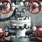
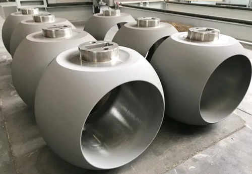
Titanium and titanium alloy valve
Titanium alloy valve is a broad concept, refers to the valve that the body and internal parts are made of titanium alloy or valves that the body material is carbon steel or stainless steel, and internal parts are made of titanium alloy valve. As well as we knew, Titanium is a reactive structural metal that reacts easily with oxygen to form a dense, stable oxide film on the surface, which can react with oxygen to regenerate the oxide film even if it is damaged. It can resist the erosion of a variety of corrosive mediums and provides a better corrosion and strength solution than that made of stainless steel, copper or aluminum valves.
The features of titanium alloy valve
- Good corrosion resistance, lightweight and high mechanical strength.
- It is almost noncorrosive in the atmosphere, freshwater, seawater, and high-temperature water vapor.
- It has good corrosion resistance in royal water, chlorine water, hypochlorous acid, wet chlorine gas and other media.
- It is also very resistant to corrosion in alkaline media.
- It is highly resistant to chlorine ions (CI) and has excellent corrosion resistance to chloride ions.
- Corrosion resistance in organic acids depends on the degree of reduction or oxidation of the acid.
- Corrosion resistance in reducing acids depends on the presence of a corrosion inhibitor in the medium.
The applications of titanium valve
- Aerospace
Titanium and titanium alloy valves can be widely used in the aerospace field because of high strength ratio, corrosion resistance. The pure titanium and titanium alloy Ti-6Al-4V control valve, stop valve, check valve, needle valve, plug valve, ball valve, butterfly valve, etc. are widely used in aircraft pipelines.
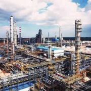
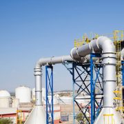
- Chemical industry
Sometimes in Chlor-alkali, salt, synthetic ammonia, ethylene, nitric acid, acetic acid and another strong corrosion environment, titanium alloy valve that has better corrosion resistance can replace common metals such as stainless steel, copper, aluminum, especially in the control and regulation of the pipeline.
- Warships
Russia is one of the first countries in the world using titanium alloy for warships. From the 1960s to the 1980s, Russia produced a series of attack submarines of which used a large number of titanium alloy pipes and valves in its seawater system.
- Power plant
Most nuclear power plants are built on the coast and titanium valves are used in nuclear power projects due to their excellent corrosion resistance to seawater. The types include a safety valve, pressure reducing valve, globe valve, diaphragm valve, ball valve, etc.
In addition, as a special medium and environment fluid control equipment, titanium valves are also used in the paper industry, food and pharmaceutical manufacturing and other fields.
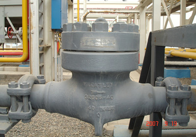
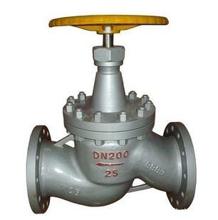 The check valve, globe valve, ball valve, and other valves can be used in ammonia and liquid ammonia piping system. These valves bring the gas pressure down to a safe level and pass it through other valves to the service system. Among them, the most commonly used is the globe valve. Ammonia globe valve is a kind of force-sealing valve, that is, when the valve is closed, the pressure must be applied to the disc so that the sealing surface are leak-free.